37
download, first user flash is erased, then the application code programmed into the flash and
at the end the complete flash is read back. This last step is required since the code memory can
be no longer read once the MCU is in the debug mode. Beside of the user flash, the SP41 has
also the Firmware ROM which cannot be read by the debugger.
After the debug download, the MCU is reset again since it was in the programming mode
during the debug download. This means a power off/on sequence is initiated again and the
debug mode selected. This same sequence is also applied when debug reset command is
executed from winIDEA
TM
.
During the debugging (the MCU in the debug mode) two hardware execution breakpoints are
available. No software breakpoints in flash are available since the user flash cannot be
modified in the debug mode.
Real time access is not available.
On-chip debug logic does not implement a stop command. Therefore the MCU cannot be
stopped by the debugger while the application is running. The MCU will stop only if hardware
execution breakpoint is hit.
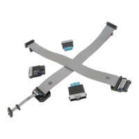
Note: The 4-pin “connector” located on the side of the debug adapter is meant for future
extensions of debug functionalities. Currently it provides no functionality.
The debug adapter connects to the target via a 6-pin 2.54 mm connector, LUMBERG: 2,5 MBX
06. A target should feature a matching part, for example WÜRTH ELEKTRONIK: 613 006 111 21.