20
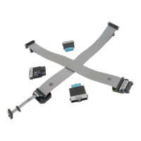
20-pin 1.27 x 2.54 mm Compact TI-20 Debug Adapter features resettable fuses on all pins
except for pin 9, 13, 14, 17-19. These fuses protect debug signals against overcurrent and cycle
back to a conductive state after the excessive current fades away. Signals on pins 13, 14, 17-19
are protected via 100 ohm serial resistors.
Jumpers J1 and J2
Jumpers J1 and J2 selects whether the EMU0 (J1) or the EMU1 (J2) is tied to pull-up (position 1-
2) or directly to the GND (position 2-3).
The EMU signals’ functions may vary from board to board. See target board manual and
schematics for more information on how to set the jumpers.
The debug adapter connects to the target via a 20-pin 1.27 x 2.54 mm connector, for example
Sullins Connector Solutions: SFH41-PPPB-D10-ID-BK. A target should feature a matching part,
for example Samtec FTR-110-51-G-D-P.