T1AL 250V
CH1 CH2
MUTE
LAN IN
EMC
IN
AUX
IN
OUT
LINE
3
EMC
COM
OUTPUT
HOT
HOT
INPUT
COM
EMC
COM
OUTPUT
HOT
HOT
INPUT
COM
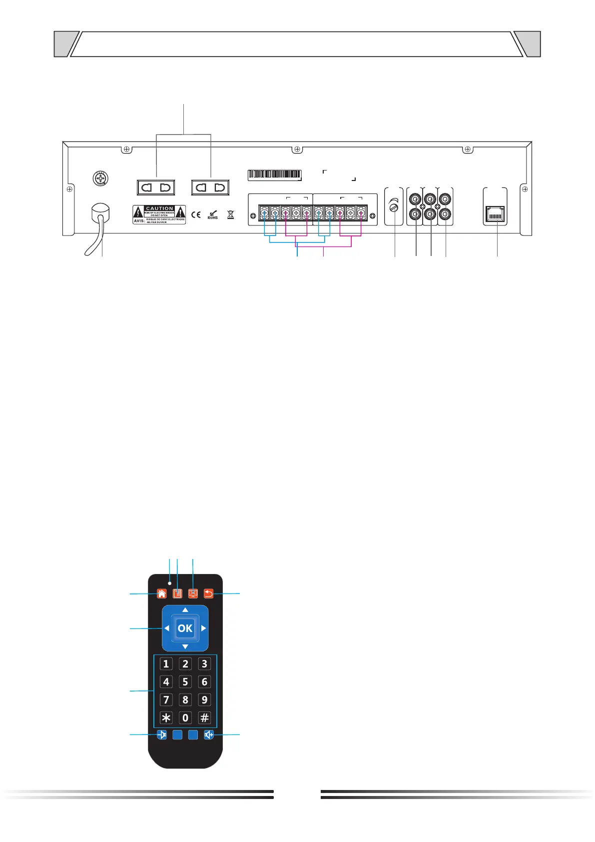
4. NOMENCLATURE AND FUCTIONS
4.2 Rear panel
7
1. AC power input.
2. CH1/CH2 signal input port
Connecting with 100V output terminal of the amplifier.
3. CH1/CH2 three-wire delay alarm port
Connecting with three-wire volume control.
4. Mute potentiometer, turn the knob to the rightmost, the mute level is the maximum; And turn the knob
to the leftmost; the mute level is the minimum.
5. AUXIN
Audio source input jack, the unbalance connecting port.
6. EMC
Emergency alarm music signals input. The equipment will take the priority to play the music
automatically once there is signal input of EMC channel.
7. 2 channel line output, unbalance output port.
8. LAN IN
connecting with EtherNet port/switch by internet cable.
9. 2 channel independent power outputs correspond to 2 independent channels.
1 2
9
3
4
5
8
6
7
4.3 Remote control
1. Back to Main Menu
2. Confirm button/up/down/left/right
select direction button
3. Number button 0-9, button*, button#
4. Volume reducing button
5. Volume increasing button
6. Return button
7. Work status indicator
8. Reserved function button
9. Stop button
1
2
3
4
5
6
7
8
9