C. AC Output Indicator
Will illuminate green to show that the inverter is outputting
240VAC power.
D. Inverter Load Indicator
Displays the approximate load being drawn from the inverter.
E. DC Power Indicator
Will illuminate green to show that DC power is being supplied to
the inverter.
F. Battery Capacity Indicator
Displays the approximate remaining capacity of the battery
running that is connected to the inverter.
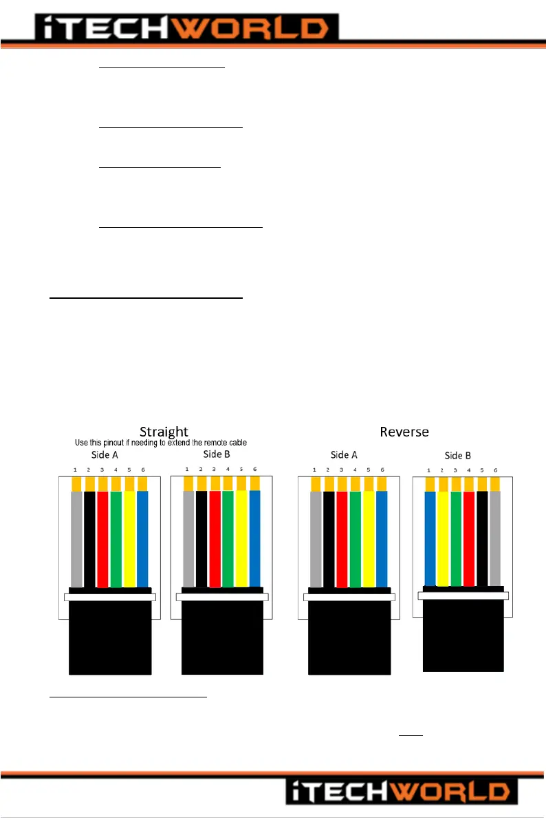
Connecting the remote control
The remote control is connected to the inverter with the communications
cable, the communications cable supplied with the purchase of the
remote control. The cable is a 6-conductor RJ11 cable (the pinout of the
connector is a Straight Pinout and NOT Reverse, refer to the image
below). The cable is connected to the RJ-11 ports found on the rear of the
remote and on the front panel of the inverter (Port F in figures 1 and 2).
Using the remote control
When using the remote control to turn the inverter on or off, please make
sure the Main Switch on the inverter front panel is in the OFF position, or
the remote-control main switch will not work.