Do you have a question about the Iwatsu CS-3000 Series and is the answer not in the manual?
General notices regarding the manual and instrument updates.
Lists the publication dates and edition numbers of the manual.
Crucial guidelines to ensure safe operation and prevent injury or damage.
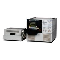
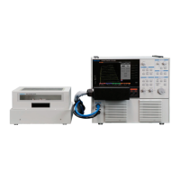
Lists the primary curve tracer unit included in the package.
Details the specific test fixtures provided for different models.
Lists all standard accessories shipped with the instrument.
Details optional accessories available for purchase and use.
Describes the structure and content of different sections within the manual.
Explains how step-by-step procedures are presented in the manual.
Illustrates examples of instrument settings and measurement processes.
Clarifies the presentation of warnings, cautions, and memos.
Provides examples demonstrating the use of cautions and memos.
Highlights key features of the CS-3000 series curve tracer, including voltage, current, and modes.
Details the instrument's support for remote control via LAN interface.
Identifies and describes the main parts and controls on the front panel of the instrument.
Explains the operation and function of the front panel's dedicated keys and rotary knob.
Details the controls and functions of the STEP GENERATOR part on the front panel.
Describes the components and functions of the COLLECTOR SUPPLY section.
Explains the function and operation of the LOOPING COMPENSATION key.
Details the function of the MEASUREMENT controls like REPEAT, STOP/SINGLE, and SWEEP.
Describes the functions of the controls related to the instrument's display settings.
Explains the functions of the SYSTEM controls for various instrument settings.
Identifies and describes the parts located on the rear panel of the instrument.
Details the parts and functions of the CS-302 test fixture.
Lists and describes the specific parts of the CS-302 test fixture.
Describes the CS-500 blank adapter for custom connections.
Details the parts and functions of the CS-301 test fixture.
Lists and describes the specific parts of the CS-301 test fixture.
Describes the optional CS-501A TO type test adapter.
Details the parts and functions of the CS-501A TO type adapter.
Describes the optional CS-502 axial type test adapter.
Details the parts and functions of the CS-502 axial type adapter.
Describes optional surface mount adapters CS-503, CS-504, and CS-505.
Details the parts and functions of the CS-503 adapter.
Details the parts and functions of the CS-504 adapter.
Details the parts and functions of the CS-505 adapter.
Describes the optional CS-506 surface mount adapter.
Details the parts and functions of the CS-506 adapter.
Describes optional surface mount adapters CS-507 and CS-509.
Details the parts and functions of the CS-507 adapter.
Details the parts and functions of the CS-509 adapter.
Describes the optional CS-508 SMD CHIP type test adapter.
Details the parts and functions of the CS-508 adapter.
Describes the optional CS-510 surface mount test adapter.
Details the parts and functions of the CS-510 adapter.
Outlines the general sequence of operations for performing measurements.
Provides instructions for properly setting up the instrument in its environment.
Details the necessary steps and connections before starting any measurement.
Instructions for correctly connecting the instrument's power cord.
Describes how to connect the test fixture to the main instrument unit.
Explains the safety interlock function to prevent operation under unsafe conditions.
Details the procedure for connecting the patch panel for the CS-302 test fixture.
Describes connection methods without using the patch panel for HIGH VOLTAGE and CURRENT.
Step-by-step guide for connecting a device using the CS-500 adapter.
Step-by-step guide for connecting a device using the CS-501A optional adapter.
Step-by-step guide for connecting a device using the CS-502 optional adapter.
Guide for connecting devices using optional adapters CS-503, CS-504, CS-505, and CS-506.
Instructions on how to properly mount the test adapter onto the test fixture.
Guide for connecting devices using optional adapters CS-507 and CS-509.
Step-by-step guide for connecting a device using the CS-508 optional adapter.
Step-by-step guide for connecting a device using the CS-510 optional adapter.
Explains the layout and components of the instrument's LCD screen.
Details the names and displayed content of various screen elements.
Explains how to use the front panel function keys and the FUNCTION knob for settings.
Provides instructions on configuring the step generator for voltage or current signals.
Details how to use the STEP knob to set voltage or current per step.
Explains the function of the STEP 1/10 key for adjusting step values.
Details how to use the OFFSET knob to set the zero step voltage or current.
Explains the function of the MENU key and its submenus for STEP GENERATOR.
Relates collector supply modes to step generator and vertical axis source.
Explains the SWEEP measurement function for the step generator.
Provides instructions on configuring collector supply parameters like mode and voltage.
Table detailing power, voltage, and current limitation resistance settings.
Explains how to use the VARIABLE knob to set collector supply output levels.
Details the function of MODE and POLARITY keys for setting measurement parameters.
Explains relationships between collector supply modes, step generator, and axis sources.
Explains the POWER-WATT key for limiting peak power and protecting the device.
Explains the function of the VOLTS key for setting maximum peak voltage.
Explains the ACQUIRE key for setting measurement parameters like frequency and sweep type.
Details the functions and settings available in the High Current mode.
Explains how to set the number of measurement points for SWEEP operations.
Explains the LOOPING COMPENSATION key for adjusting floating capacity compensation.
Explains how to select and use measurement modes: REPEAT, SINGLE, and SWEEP.
Provides detailed information and related functions for SWEEP measurements.
Explains how to use HORIZONTAL and VERTICAL knobs for axis range and source settings.
Describes axis range adjustments for the WAVE screen.
Details the operation and settings managed by the HORIZONTAL knob.
Explains how to set the BASE-EMITTER as the source for horizontal axis measurements.
Details the operation and settings managed by the VERTICAL knob.
Explains how to set the EMITTER as the source for vertical axis measurements.
Explains how to set the STEP as the source for vertical axis measurements.
Explains how to configure settings within the DISPLAY menu.
Details the functions available through the MENU key for display settings.
Explains how to toggle inverse/non-inverse display of waveforms using the INVERT key.
Explains the VIEW/PULSE key for selecting trace/wave modes and setting pulse parameters.
Details range settings for Vbe, Vce, and Ic when VIEW MODE is set to WAVE.
Explains the settings for F4 (PULSE WIDTH) and F5 (MEASUREMENT POINT) keys.
Explains the CURSOR key for enabling cursor display and selecting cursor types.
Details how to use the DOT cursor for measuring points on characteristic curves.
Explains the fLINE cursor for displaying gradients and measuring resistance or transconductance.
Details the FREE cursor for arbitrary coordinate selection and calculation.
Explains the WINDOW cursor for measuring rectangular areas and parameters like beta or gm.
Explains the ZOOM key for magnifying specific areas of the waveform display.
Explains the POSITION key for setting the origin of the characteristic curve.
Details the movable range of positions when the ZOOM function is active.
Introduces the SYSTEM menu structure and its submenus.
Explains the UTILITIES submenu and its various functions.
Details the settings for remote control, including DHCP and IP address configuration.
Explains settings for file type, background color, and file naming for hard copies.
Details settings for adjusting waveform, grid, cursor, REF, and backlight brightness.
Explains options within SYSTEM SETUP, including beep, power-on, panel lock, and header.
Details how to configure header information like date, comment, and connection status.
Explains how to set the instrument's date and time.
Details how to use the TEXT EDIT submenu to set comments for the header.
Step-by-step instructions for creating and entering comments.
Explains the MEASUREMENT SETUP submenu for configuring measurement actions.
Details the settings on the first page of the MEASUREMENT SETUP submenu.
Details the settings on the second page of the MEASUREMENT SETUP submenu.
Explains the options available within the SYSTEM TOOLS submenu.
Provides the procedure and cautions for initializing the instrument's system settings.
Explains the process and precautions for updating the instrument's software.
Step-by-step instructions for updating the instrument's software.
Explains the procedure and precautions for installing optional software.
Step-by-step instructions for installing optional software from USB.
Describes messages and actions when an option is already installed.
Explains potential causes and solutions for installation errors.
Explains how to use the COPY key to execute hard copy and save screen images.
Explains the SAVE/RECALL/DELETE key for managing instrument data.
Details the options and procedures for saving instrument data.
Explains the functions for saving SETUP, TRACE, and REF data.
Details the options and procedures for recalling instrument data.
Explains the functions for recalling SETUP, TRACE, and REF data.
Step-by-step instructions for selecting files from the USB memory for recall.
Details the options and procedures for deleting instrument data.
Explains procedures for saving, recalling, and deleting data types and memory.
Details the procedures for saving SETUP, TRACE, and REF data.
Details the procedure for saving REF data into USB memory.
Details the procedures for recalling SETUP, TRACE, and REF data.
Explains how to recall the instrument's default settings.
Details the procedure for recalling TRACE data from USB memory.
Details the procedure for recalling REF data from USB memory.
Details the procedures for deleting SETUP, TRACE, and REF data.
Details the procedure for deleting REF data from USB memory.
Details the procedure for deleting REF data from internal memory.
Explains the procedure and cautions for formatting USB memory.
Explains how to set terminal connections using the CONFIGURATION key.
Illustrates internal connection diagrams for various configuration settings.
Explains how measured device and axis settings interact based on range.
Explains the AUX key for setting output voltage to the auxiliary output.
Explains the APPLICATION key and the need for optional software installation.
Describes the outline and application of the CS-800 semiconductor parameter search option.
Explains the LIMIT SWEEP function for restricting measurement values.
Describes the function for continuously applying constant voltage or current.
Provides an example of parameter search for an IGBT module.
Explains the usage and function of the DOUBLE SWEEP option CS-801.
Details the Vth/hFE SETUP submenu for semiconductor parameter search.
Details the COLLECTOR SUPPLY SETUP submenu for sweep range configuration.
Details the STEP GENERATOR SETUP submenu for sweep range configuration.
Explains the LIMIT SWEEP submenu for restricting measurement values.
Details the CONSTANT VOLT / CURR submenu for applying constant voltage or current.
Details the COLLECTOR SUPPLY SETUP submenu for setting sweep parameters.
Details the OBSERVATION SETUP submenu for setting upper/lower limit values.
Details the COLLECTOR SWEEP DOUBLE submenu for observing hysteresis.
Explains the instrument's default settings for various functions.
Lists functions and their default settings that can be recalled.
Lists functions and their default settings that are not recalled.
Details the default settings for application-specific parameters.
Continues the list of default settings that are not recalled.
Details the recall settings related to deleting data.
Provides a basic guide to understanding instrument operation and preparing for measurements.
Explains how to measure diode characteristics like forward voltage and ON resistance.
Details the specific steps for performing diode measurements.
Continues the detailed steps for performing diode measurements.
Explains the procedure for measuring the ON resistance of a diode.
Details the steps for measuring diode ON resistance using cursors.
Explains how to measure the reverse characteristics (breakdown) of a diode.
Details the steps for measuring diode reverse characteristics.
Introduces examples of measuring transistor characteristics like IC-VCE.
Explains the procedure for measuring IC vs. VCE characteristics of a transistor.
Details the steps for measuring IC vs. VCE characteristics.
Continues the steps for measuring IC vs. VCE characteristics.
Explains the procedure for measuring the DC current amplification factor (hFE).
Details the steps for measuring the DC current amplification factor (hFE).
Explains the procedure for measuring IC vs. VBE characteristics of a transistor.
Details the steps for measuring IC vs. VBE characteristics.
Explains the procedure for measuring IC vs. IB characteristics of a transistor.
Details the steps for measuring IC vs. IB characteristics.
Explains the procedure for measuring IB vs. VCE characteristics of a transistor.
Details the steps for measuring IB vs. VCE characteristics.
Introduces examples of measuring FET characteristics like ID vs. VDS.
Explains the procedure for measuring ID vs. VDS characteristics of FETs.
Details the steps for measuring ID vs. VDS characteristics of FETs.
Continues the steps for measuring ID vs. VDS characteristics.
Explains the procedure for measuring ID vs. VGS characteristics of FETs.
Explains measuring ON resistance and transconductance (gm) of FETs.
Details steps for measuring ON resistance and transconductance (gm) of FETs.
Explains measuring ID vs. VGS and forward transfer admittance of FETs.
Details steps for measuring forward transfer admittance of FETs.
Explains setting SWEEP measurement for FET characteristics.
Explains measuring IGBT characteristics like saturation voltage and forward voltage.
Shows how to connect an IGBT device to the test fixture.
Details the steps for measuring IGBT characteristics.
Explains how to check pulse waveforms in WAVE mode.
Describes steps to perform after checking waveforms, including setting sweep parameters.
Explains how to measure the forward voltage (VFM) of an IGBT.
Covers routine tasks for maintaining the instrument's condition.
Provides instructions for cleaning the dust filter on CS-3200/CS-3300 models.
Recommends regular calibration for accurate measurements and provides contact information.
Details the process for contacting support, warranty repairs, and shipping instructions.
Provides guidelines on proper storage conditions and transportation methods.
Lists the technical specifications of the instrument.
Details specifications for the step generator and vertical axis.
Lists specifications for horizontal axis, display, and cursor measurement functions.
Details physical dimensions, mass, and environmental operating conditions.
Lists all accessories that are included with the instrument.
Lists the compliance standards met by the instrument.
Provides dimensional drawings for the CS-3100 main unit.
Provides dimensional drawings for the CS-3200/CS-3300 main units.
Provides dimensional drawings for the CS-302 test fixture.
Provides dimensional drawings for the CS-500 blank adapter.
Provides dimensional drawings for the CS-301 test fixture.
Provides dimensional drawings for the CS-501A TO type adapter.
Provides dimensional drawings for the CS-502 axial type adapter.
Provides dimensional drawings for the CS-503 surface mount adapter.
Provides dimensional drawings for the CS-504 surface mount adapter.
Provides dimensional drawings for the CS-505 surface mount adapter.
Provides dimensional drawings for the CS-506 surface mount adapter.
Provides dimensional drawings for the CS-507 surface mount adapter.
Provides dimensional drawings for the CS-508 SMD CHIP adapter.
Provides dimensional drawings for the CS-509 surface mount adapter.
Provides dimensional drawings for the CS-510 surface mount adapter.
| Number of Channels | 2 |
|---|---|
| Bandwidth | 100 MHz |
| Vertical Sensitivity | 5 V/div |
| Timebase | 0.5 s/div |
| Trigger Modes | Auto, Single |
| Display | 6 inch CRT |