EasyManua.ls Logo

Iwatsu SC7101 - Page 18

Default Icon
30 pages
Print Icon
To Next Page IconTo Next Page
To Previous Page IconTo Previous Page
Loading...
SC-7101/SC-7102
Section
3
Measuring
Procedures
Errors
in
Measurement
When
average
values
of
input
signals
during
Fi
:
-
Errors
in
frequency
measurements,
there
are
N
period
are
measured:
igure
3-3-2.
Frequency
and
Error
in
Frequency
Measurement
I
errors
due
to
accuracy
of
the
reference
oscil-
2a
1
En
1
(Sinewave;
when
S/N
is 40
dB)
(SC-7101)
lator",
"+
1
count
error"
and
the
"Trigger
error".
NT
7
*
es
*
Ww
.
Showing
1/N
reduction
in
error.
Consequently,
Error
due
to
accuracy
of
the
reference
oscil-
measurements
of
average
values
of
various
periods
My
lator":
are
advantageous
as
they
can
reduce
influence
Since
the
counting
time
(gate
time)
of
the
of
noise.
+
10
MHz
or
more
frequency
measurement
are
determined
by
dividing
1
kH2/1
ms,
10
H2/O.1
sy
1
Hz/1
5,
O61
Hz/10
s
the
oscillation
frequency
of
the
reference
oscil-
How
do
these
errors
appear
in
the
actual
mea-
10
fie
on
Less:
lator
(crystal
oscillator),
this
error
depends
surement.
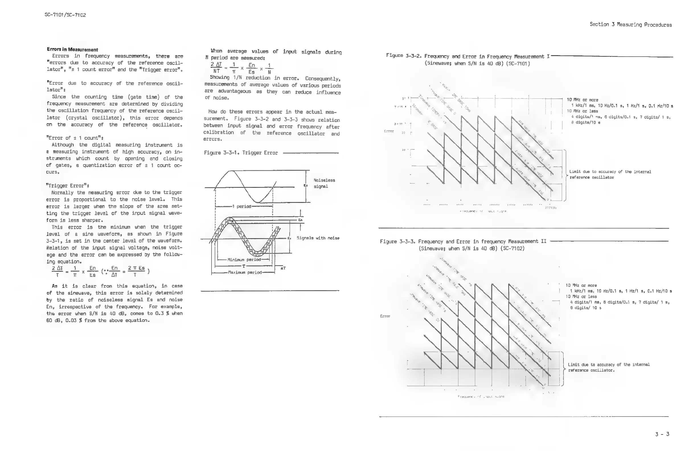
Figure
3-3-2
and
3-3-3
shous
relation
‘an
aah
ria
tack
aca
shee
on
the
accuracy
of
the
reference
oscillator.
between
input
signal
and
error
frequency
after
cee
calibration
of
the
reference
oscillator
and
[
"Error
of
+
1
count":
errors.
Although
the
digital
measuring
instrument
is
a
measuring
instrument
of
high
accuracy,
on
in-
Figure
3-3-1.
Trigger
Error
[
struments
which
count
by
opening
and
closing
of
gates,
a
quantization
error
of
+
1
count
oc-
curs.
Limit
due
to
accuracy
of
the
internal
reference
oscillator
Noiseless
Es
signal
"Trigger
Error":
Normally
the
measuring
error
due
to
the
trigger
error
is
proportional
to
the
noise
level.
This
error
is
larger
when
the
slope
of
the
area
set-
———1
period
4
eale
ting
the
trigger
level
of
the
input
signal
wave-
form
is
less
sharper.
This
error
is
the
minimum
when
the
trigger
level
of
a
sine
waveform,
as
shown
in
Figure
3-3-1,
is
set
in
the
center
level
of
the
waveform.
Relation
of
the
input
signal
voltage,
noise
volt-
age and
the
error
can
be
expressed
by
the
follow-
ing
equation.
2aT
1,
£0
(..fn
27s,
Teo
Es
at”
TT
A
i
H
H
H
H
1
.
Signals
with
noise
Figure
3-3-3.
Frequency
and
Error
in
frequency
Measurement
II
(Sinewave;
when
S/N
is
40
dB)
(SC-7102)
Maximum
period
-——|
10
MHz
or
more
|
1
kHz/1
ms,
10
Hz/0.1
s,
1
H2/1
s,
0.1
Hz/10
s
10
Mz
or
less
4
digits/1
ms,
6
digits/0.1
s,
7
digits/
1
s,
8
digits/
10
s
As
it
is
clear
from this
equation,
in
case
of
the
sinewave,
this
error
is
solely
determined
by
the
ratio
of
noiseless
signal
Es
and
noise
En,
irrespective
of
the
frequency.
For
example,
the
error
when
S/N
is 40
dB,
comes
to
0.3
%
when
ghee
60
cB,
0.03
%
from
the
above
equation.
Limit
due
to
accuracy
of
the
internal
reference
oscillator.
OOMHE
OH:
100Hz~=—«sTkHz
~=—«10kHz_-—=«100kHz»=«
MHz
©
10MHe
200MHz