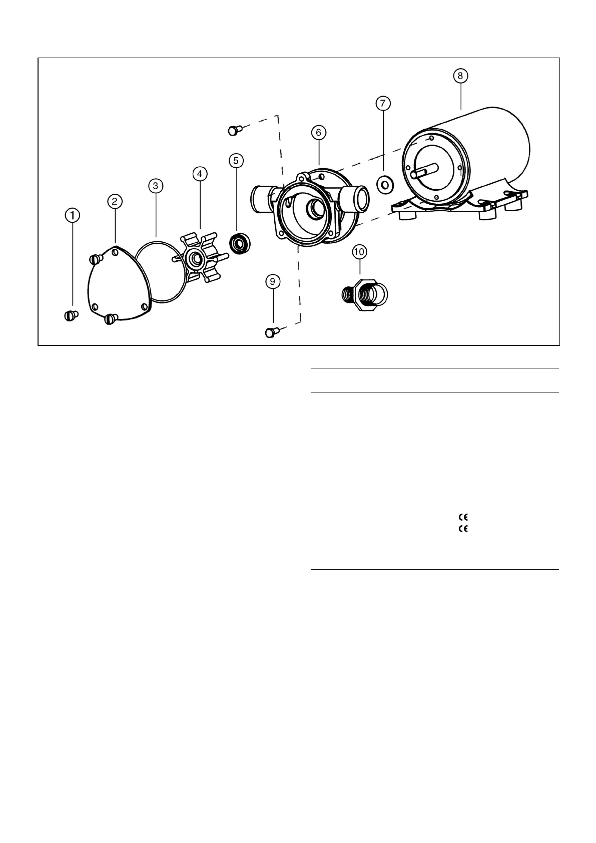
PARTS LIST
Part
Key Description Qty. Number
1 Screw Kit (End Cover) 1 91004-0090
(4 screws/kit)
2 End Cover 1 18647-0000
3 O-Ring* 1 18753-0660
4 Impeller* 1 6303-0003
5 Seal* 1 18753-0384
6 Body
†
1 18645-0000
7 Slinger 1 6342-0000
8 Motor 1
Model 18670-0123 12V 18753-0050
Model 18670-0923 12V 18753-0659
Model 18670-0943 24V 18753-0051
9 Screw (Pump to Motor) 2 98019-0020
10 Port Adapter Kit (2 each) 1 18753-0103
Service Kit 90061-0031
* Parts Contained in Service Kit.
† When replacing a pump body that uses a round end cover (3 hole
pattern) it is also necessar y to replace the end cover, screws and
replace the gasket with an O-ring (order keys 1, 2 & 3).
MAINTENANCE
Check wires and connections to be sure corrosion is
not adding additional resistance to the motor circuit
and causing a low voltage condition at the motor. Low
voltage can inhibit motor from starting and cause
fuse to blow. Full voltage should be available to prevent
motor damage.
NOTICE: If pump is idle for extended periods, the impeller
may stick to the pump body, preventing motor rotation
and causing blown fuses. To correct, remove end cover
and impeller, clean body and impeller, then lubricate with
water or small amounts of grease before assembly.
If pump is to be in freezing temperatures, drain by
loosening end cover screws.
A Service Kit, or at least spare impellers, should be
carried aboard to be assured of pumping capability.
DISASSEMBLY
1. Remove end cover screws, end cover and O-ring.
2. Withdraw impeller.
3. Loosen and remove two slotted hex screws, which
attach body to motor.
4. Tap body lightly between ports and remove body
from
motor.
5. With a 1/2" diameter dowel, push against the shaft
seal from back (motor) side of the body to dislodge
it from the seal bore.
NOTE: Do not tamper with or disassemble motor.
ASSEMBLY
1. Lubricate seal with water and position it in seal bore
with lip, or hollowed-out side of seal, pointing
towards the impeller bore. With a 1/2" diameter
dowel, push against the shaft seal into its bore until
it contacts the bottom.
2. Lubricate motor shaft and install body on motor.
3. Lubricate impeller bore and, aligning flat in impeller
with flat on motor shaft, install impeller with clock-
wise rotary motion.
4. Install O-ring, end cover and screws.
EXPLODED VIEW
 Loading...