PARTS LIST
Qty. Part
Key Description Req. Number
1 Motor Cover† 1 43990-0051
2 Clamp 1 18753-0044
3 Hose 1 29035-0001
4 Bowl Installation Hardware 1 18753-0637
4A Hex Head Screw** 4
4B Starlock Washer** 4
4C Hex Nut (two places)** 8
4D Washer, Plastic** 4
4E Washer, Stainless Steel**
4F Nut Cap** 4
5 O-Ring 1 44101-1000
6 Base Assembly** 1 37004-1000
7 Screw Covers (3/kit) 1 37003-0000
8 1-1/2" Adaptor, Discharge Port 1 98023-0080
91" Discharge Port** 1 44107-1000
10 Joker Valve* ** 1 44106-1000
11 Screw** 3 96050-0568
12 Chopper Plate† with Lock Nut 1 37056-1000
13 Macerator Housing † 1 37014-0000
14 Centrifugal Impeller † 1 37006-0000
15 Set Screw † 1 18753-0492
16 O-ring*† 1 43990-0066
17 Screw Short † 2 91009-0096
18 Screw Long † 2 91010-0130
19 Washer, Plastic*† 2 35445-0000
20 Sealing Sleeve † 1 37036-1000
Qty. Part
Key Description Req. Number
21 Wearplate ‡ 1 37018-0000
22 Lock Washer #10, Stainless Kit † 4
23 Screw † 4 91027-0011
24 Gasket*† 1 12558-0000
25 Flexible Impeller*† 1 6303-0003
26 Body † 1 12554-0000
27 Seal & Retainer*† 1 1040-0000
28 Slinger † 1 6342-0000
29 Motors:
Motor - 12 Volt † 1 37064-0000
Motor - 12 Volt EMC † 1 37064-0900
Motor - 24 Volt † 1 37065-0000
Motor - 24 Volt EMC † 1 37065-0900
30 Adaptor 2 93003-0240
31 Switch & Plate 1 37020-0000
Service Kit 37040-0000
Motor/Pump Assy. 12V † 37041-0010
Motor/Pump Assy. 12V EMC † 37041-0910
Motor/Pump Assy. 24V † 37041-0011
Motor/Pump Assy. 24V EMC † 37041-0911
‡ Wearplate #21 includes Shaft Sealing Sleeve #20 and
Pump/Base O-ring #16.
† Parts included in Motor-Pump Assembly.
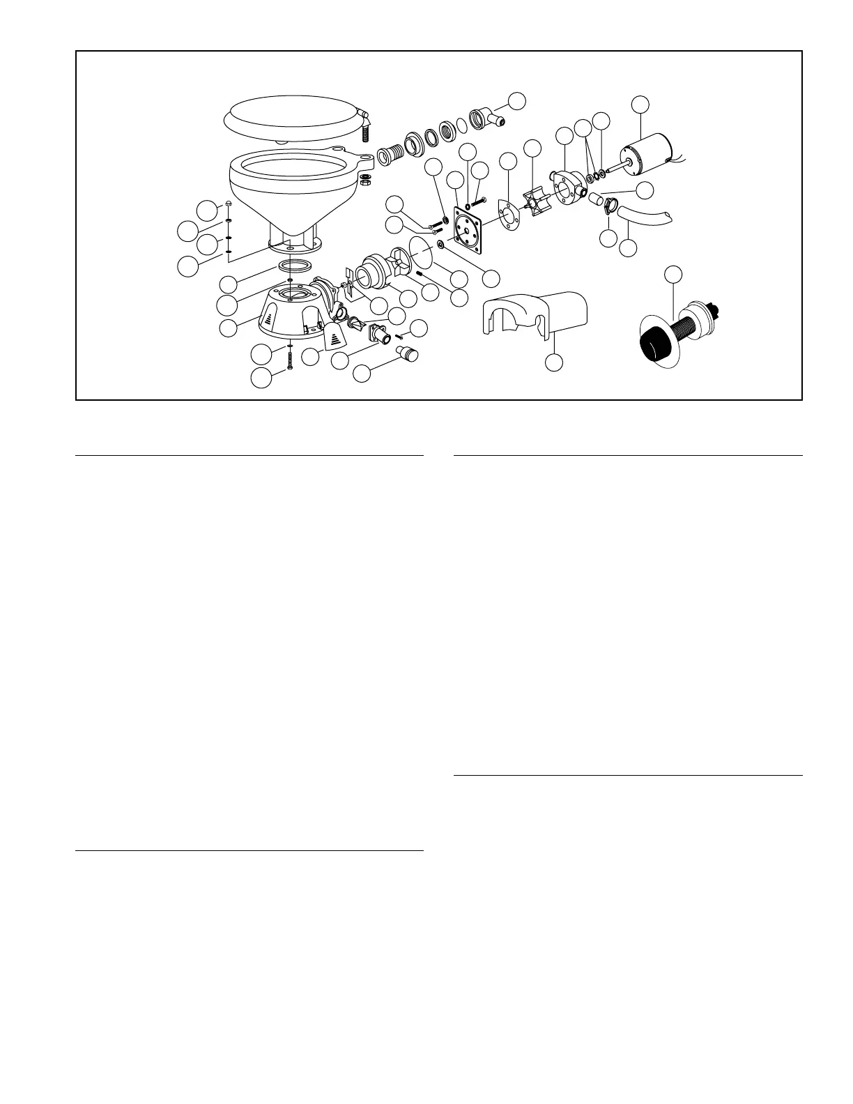
EXPLODED VIEW
Disconnect pump inlet and discharge hoses. Remove four
screws, Key No. 23, pull out complete motor, pump and
macerator assembly. Remove macerator housing from base.
Remove discharge port, Key No. 9, and inspect joker
valve. Unscrew chopper plate lock nut, Key No. 12, by
turning counterclockwise, facing plate and remove
chopper. Prevent shaft from turning by inserting a screw-
driver in slot of shaft protruding from rear of motor.
Loosen centrifugal impeller set screw and slide impeller
off motor shaft.
Remove four flathead screws, Keys No. 17 & 18,
wearplate, Key No. 21, shaft sealing sleeve, Key No. 20,
gasket, Key No. 24; then slide pump assembly off motor
shaft. Replace all worn or damaged parts, clean remain-
ing parts.

 Loading...