3
gasket,KeyNo.24;thenslidepumpassemblyoffmotor
shaft. Replace all worn or damaged parts, clean
remainingparts.
REASSEMBLY INSTRUCTIONS
Presssealintobodywithlipfacingimpeller;becareful
nottococksealinbore.Installpumpbodyonmotorand
positiononregister; lubricateimpeller borewithpump
grease. Install impeller, gasket and wearplate. Make
sure gasket surfaces are clean and smooth. Tighten
wearplatescrews.Slideshaftsealingsleeveontoshaft
and seat in its bore inwearplate. Relocatecentrifugal
impellerabout1/8”fromwearplateandsecurewithset
screw. Position macerator housing around centrifugal
impeller then put chopper plate on end of shaft and
securewith locknut. Install O-ring in O-ringgroovein
wearplatesurface(alittlegreasewillhelpholdinplace).
Aligning key on top of macerator housing with slot in
base, slide macerator assembly into base. Secure
pumpassemblywiththefourscrews.
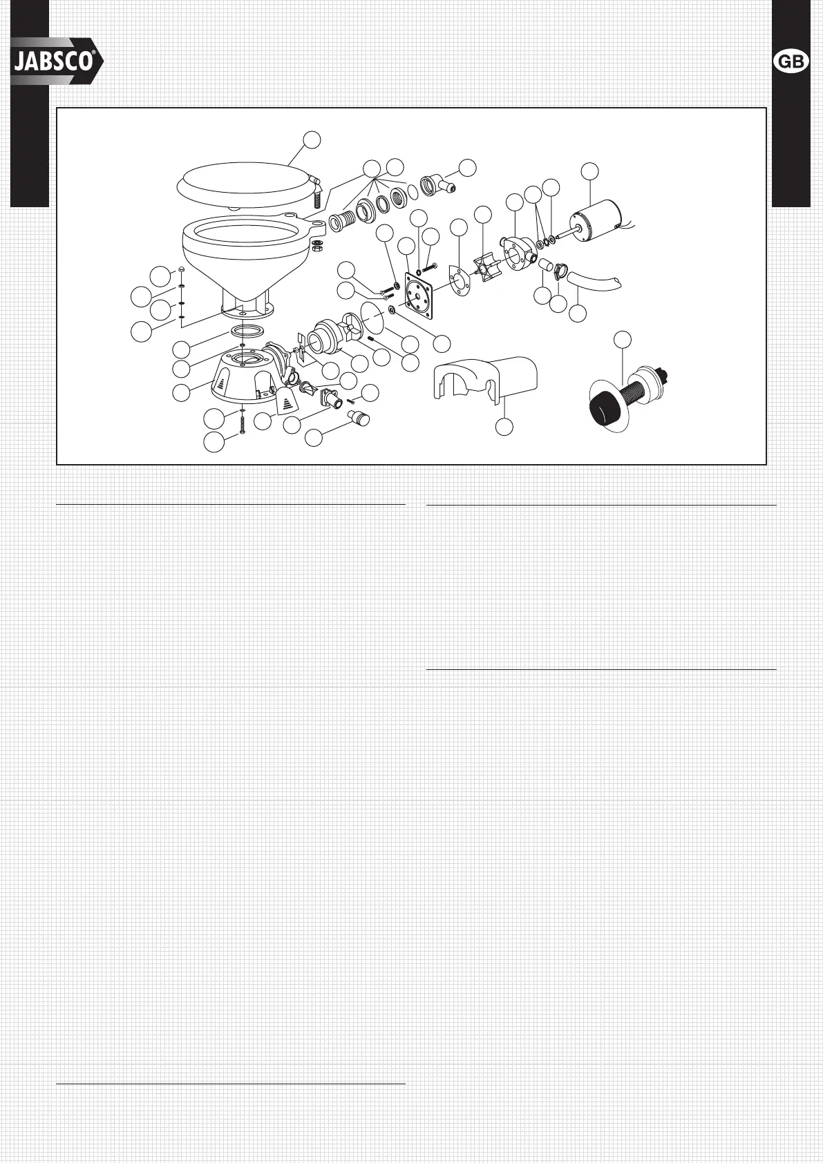
PARTS LIST
Key Description Qty. Part Number
1 Seat,LidandHingeSet 1
CompactToilet 29097-1000
RegularToilet 29127-1000
1A HingeSet(1Pair) 1
CompactToilet 29098-1000
RegularToilet 29098-2000
2 Bowl,CompactSize 1 29096-0000
Bowl,RegularSize 1 29126-0000
3&4 BowlSpud&Intake 1 29048-0000
Elbow&O-ring
5 Clamp 1 18753-0044
6 Hose 1
29035-1001
7 BowlInstallationHardware 1 18753-0637
7A PhillipsHeadScrew** 4
7B Washer,Starlock** 4
7C HexNut**(twoplaces) 4
7D Washer,Plastic** 4
7E WasherStainlesssteel** 8
7F NutCap** 4
8 O-RingBowl/Seal 1 44101-1000
9 BaseAssembly** 1 37004-1000
10 1-1/2"Adaptor,DischargePort 1 98023-0080
11 JokerValve*** 1 44106-1000
12 1"DischargePort** 1 44107-1000
13 Screw** 3 96050-0568
14 ChopperPlate†withLockNut 1 37056-1000
15 MaceratorHousing† 1 37014-0000
16 CentrifugalImpeller† 1 37006-0000
17 SetScrew† 1 18753-0492
18 O-ring*† 1 43990-0066
19 SealingSleeve† 1 37036-1000
20 Screw† 2 91009-0096
21 Screw† 2 91010-0130
22 Washer,Fiber*† 2 35445-0000
23 WearplateKit‡† 1 37018-0000
24 LockWasher#10,StainlessKit† 4
25 Screw† 4 91027-0011
26 Gasket*† 1 12558-0000
27 FlexibleImpeller*† 1 6303-0003
28 Body† 1 12554-0000
29 Seal&Retainer*† 1 1040-0000
Key Description Qty. Part Number
30 Slinger† 1 6342-0000
31 Motors:
Motor-12VoltEMC† 1 37064-0000
Motor-24VoltEMC† 1 37065-0000
32 Adapter 2 93003-0240
33 Switch&Plate 1 37020-0000
34 MotorCover† 1 43990-0051
35 ScrewCover(3each) 1 37003-1000
ServiceKit 37040-0000
Motor/PumpAssy.12VEMC† 37041-0010
Motor/PumpAssy.24VEMC† 37041-0011
* PartsSuppliedwithServiceKit37040-0000.
** Partsincludedwithbase37004-1000.
‡ Wearplate#23includesSealingSleeve#19andPump/
BaseO-ring#18.
† PartsincludedinMotor-PumpAssembly.
O
T
H
S
U
P
F
L
U
S
H
T
R
I
C
C
E
L
E
T
O
I
L
E
T
8
9
10
11
14
12
13
21
20
4
15
16
17
18
22
23
24
25
26
27
28
29
30
31
32
5
6
3
2
7F
7C
7E
7D
7A
34
33
19
1
7B
35
7C
EXPLODED VIEW
TO
BOWL
ELBOW

 Loading...