To Waste Pump
Positive (Orange)
Motor Lead
To Solenoid
Valve/Siphon
Breaker
To Positive
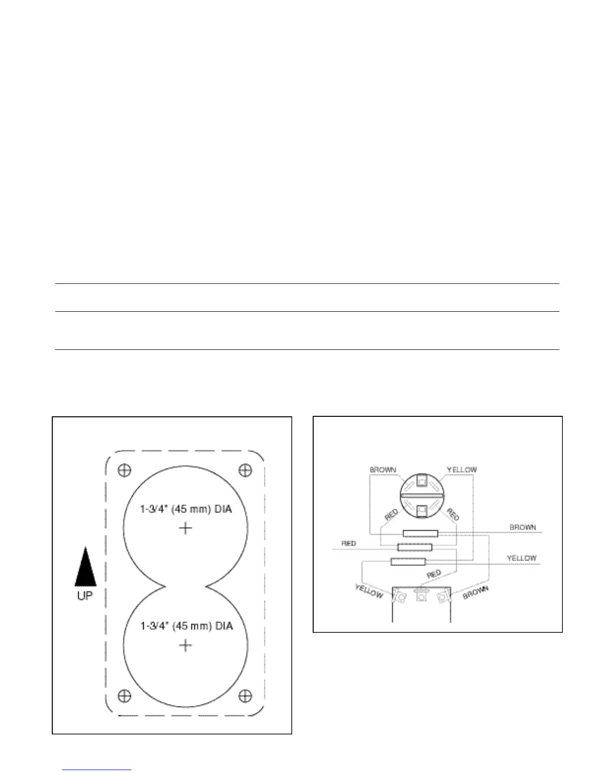
WIRING DIAGRAM
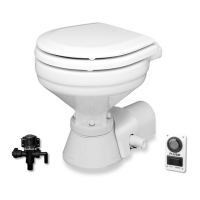
TEMPLATE
ELECTRICAL SPECIFICATIONS
Amp Fuse Wire Size Per Feet Of Run*
Voltage Draw Size 0'-10' 10'-15' 15'-25' 25'-40' 40'-60'
12 Vdc 10 25 #16 #14 #12 #10 #8
24 Vdc 5 15 #16 #16 #16 #14 #12
32 Vdc 4 10 #16 #16 #18 #14 #12
* Length of run is total distance from power source to product and back to ground.
ELECTRICAL
The electrical wiring should be independent of all other
accessories. It should be made with marine grade
copper stranded wire of the gauge specified in the
electrical specifications chart. Make all wire connections
with mechanical locking type connectors (crimp type butt
connectors and terminals). Ensure the circuit is protected
by a proper sized fuse or circuit breaker determined from
the electrical specifications chart. Secure all wires to a
solid surface approximately every eighteen inches
(1/2m) along their entire length of run.
Wire the switch panel to the solenoid valve/siphon
breaker and toilet pump assembly as per the following
wiring diagram. Select a location for the switch panel
that is convenient to the toilet user and will also allow
access to run the wires from the switch panel to both the
toilet’s motor and the solenoid valve/siphon breaker as
well as from the electrical power source to the switch
panel. The red lead from the panel should be connected
to an over-current protected positive power source.
Connect the brown lead from the panel to the waste
pump positive (orange) motor lead. Connect the black
waste pump motor lead to battery negative. Connect the
yellow lead from the panel to a solenoid valve terminal.
Connect the remaining solenoid valve terminal to battery
negative. The solenoid valve is not polarity sensitive.
To install the switch panel, drill two 1-3/4" (45mm)
diameter holes (slightly over-lapping) through the selected
switch mounting surface per the attached template.
Ensure the template is oriented correctly because it is
not symmetrical. Also, drill four appropriate sized holes
for the fasteners selected to secure the switch panel to
its mounting surface.
 Loading...