This document is a user manual for the JACK K4-D series sewing machine, specifically a High Speed Computerized Cylinder-bed Interlock Machine.
Function Description
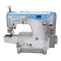
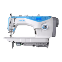
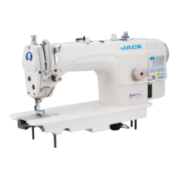
The JACK K4-D series sewing machine is a high-speed computerized cylinder-bed interlock machine designed for knitting and knitting products of the wrap seam and wrapping. It features an integrated control box within the machine head, allowing for direct adjustment of parameters and offering an interpersonal exchange mode for easy and convenient operation.
Important Technical Specifications
- Machine Name: High Speed Computerized Cylinder-bed Interlock Machine
- Model Type: K4
- Model Name: K4-D
- Stitch Type: ISO standard: 406/407/602/605
- Use: Knitting, knitting products of the wrap seam, wrapping
- Sewing Speed: Maximum speed: 5500RPM, Factory speed: 4000RPM
- Needle Width: 3 needles: 5.6mm, 6.4mm; 2 needles: 2.8mm, 3.2mm, 5.6mm, 6.4mm
- Differential Feed Ratio: 0.8-1.3
- Stitch Length: 1.5mm-4.5mm
- Needle Type: UY128GAS 11#, 14# (Standard: 11#)
- Needle Bar Stroke: 33mm
- Presser Foot Height: 7.0mm
- Volume (Carton Size): 675mm×450mm×602mm
- Volume (Machine Size): 500mm×380mm×260mm
- Weight (Net/Gross): Net weight: 52Kg, Gross weight: 62Kg
Usage Features
The machine offers various adjustable settings to optimize sewing performance for different fabrics and applications.
Installation:
- Table Size and Installation: A diagram (Figure 3-1) provides dimensions for the table and installation method.
- Chain Installation: The pedal chain is installed as shown in Figure 3-2, connecting Chain 1 to the hook and Chain 2.
Needle Installation:
- When installing the needle, the needle head must be completely inserted into the needle clamp, and the needle groove should face inwards.
Threading Method:
- Standard threading methods are illustrated for K4-D and K4-UT models (Figure 5-2). The manual also shows how threading changes when the needle thread stretching is larger (Figure 5-2) or smaller (Figure 5-3, Figure 5-4).
Stitch Length Adjustment:
- Stitch length can be adjusted within the range of 1.5mm-4.5mm. This adjustment is made by rotating the stitch length adjusting knob. Clockwise rotation increases the needle length, while counterclockwise rotation decreases it.
Differential Regulation:
- The differential feed can be adjusted within a range of 0.8-1.3. Loosen and adjust the screw to shrink (up) or stretch (down) the fabric.
Presser Foot Pressure Adjustment:
- Adjust the presser foot pressure by loosening the adjusting screw presser foot and rotating the presser foot adjusting screw clockwise or counterclockwise. Clockwise rotation increases pressure, while counterclockwise rotation lightens it.
Thread Tension Adjustment:
- Thread tension is adjusted based on the fabric, thread, thread width, and other conditions. Adjust the nut thread clamp device: clockwise to tighten, counterclockwise to loosen.
Cooler Wire Guide Adjustment:
- Loosen the tightening screw, adjust the height of each wire guide to the indicated dimension, and then tighten the screw. For different fabrics, adjust the thread taking up length by adjusting the needle thread guide height (A, B, C). Increasing the height of the wire guide increases the thread taking up quantity, and decreasing it reduces the thread taking up quantity.
Shuffling the Needle Thread Operator Adjustment:
- Release the set screw and move the needle thread operator to adjust the distance between the margin of the needle thread operator and the center of the shuffling release pole rod to 80mm. Then tighten the set screw. For various types of fabric, adjust the thread taking up length by changing this distance. Increasing the distance reduces the thread taking up length, and decreasing it increases the thread taking up length.
Adjustment of Spreader Thread Take Up:
- At the highest point, release set screw ③, make the top of the inner guide line fix to the bottom of the guider slot, then tighten the set screw ③.
Adjusting the Looper Thread Cam Guide and the Looper Thread Cam:
- When the needle is at the top, adjust the hit thread cam so that it just starts to hit the thread.
- When adjusting the base thread distance, first loosen the screw and adjust the dividing thread plate position. If the dividing thread plate moves up, the thread distance gets less, while vice versa.
Adjusting Needle Height:
- First, adjust the gap between the needle and the needle plate to ensure it is equal. Then, adjust the needle height. When the needle runs to the highest point, the height of the needle plate to the left needle pinpoint is H. Specific H parameters are provided for different models (K4-01GB×356, K4-01GB×364, K4-02BB×356, K4-02BB×364, K4-35AC×356, K4-35AC×364) for both standard (30.8mm) and high (33.4mm) stroke.
Looper Adjusting Method:
- Adjusting the distance of looper to needle: When the needle is at the lowest point, and the looper is at the right end point, the distance between the looper pinpoint to the right needle middle point is called Leading distance A. Specific A parameters are provided for different models.
- Adjusting the distance between looper and needle: When the looper moves from right to left at the needle middle, adjust the distance between the looper and needle to 0-0.05mm. As the looper continues to move towards the left, when it arrives at the middle of the left needle, the distance of the looper and left needle is 0.05-0.1mm.
Adjusting Rear Guard Needle:
- When the needle bar is at its lowest point, adjust the rear guard needle to make it on 1/3 of the right needle hole. The right end of the looper to the middle of the right needle, and the front and rear clearance of the right needle and looper should be 0-0.05mm.
Relationship Between Swing Timing Bar and Thread Loop:
- If the thread loop is too large or too small, it can lead to needle-skipping or thread-broken problems. You can adjust the swing timing bar to adjust the size of the thread loop.
- Making use of over-thread bar to adjust: Loosen the set screw, adjust the over-thread bar, moving it forward or backward. If moved forward, the thread loop gets smaller; otherwise, if moved backward, the thread loop gets larger.
Adjusting Feed Teeth Height:
- When the feed teeth reach their maximum point, loosen screw 2 and adjust the feed teeth height to 1.2mm. Then, loosen screw 1 and adjust the differential feed teeth height to 1.2mm, then tighten screw 2 and loosen screw 1, adjusting the feed teeth height to 1.2mm, and after that tighten screw 1.
Installation Position of Spreader:
- Spreader height H is the distance between the needle plate to the needle. Adjust spreader height by loosening screw 1, then move the spreader up or down. Specific H parameters are provided for different models.
- Spreader moving from right towards to left: Loosen screw 1, adjust the distance between the spreader pinpoint and left needle to be 0.5mm. The spreader continues to move towards the left to the end, then loosen screw 2, adjusting the distance between the spreader and left needle middle to be 4.5-5.0mm, next tighten screw 2.
Looper Moving Towards Left Through the Inside of All Needles:
- Adjust the distance between the needle and front guard needle to be 0.3-0.5mm. If the thread is thick or thin, ensure it can pass successfully. The front guard needle should be near to installation. Adjust the distance between the front guard needle and front guard needle protect device to 0.5mm.
Adjusting Presser Height:
- When adjusting presser height, adjust the screw height to avoid the presser touching other spare parts, and then fix it with the nut.
Maintenance Features
Lubrication and Oiling:
- Factory Refueling: When the machine is shipped from the factory, the oil is discharged. Before using the sewing machine for the first time, add oil 22# by opening the plug marked with OIL. Fill oil between the upper and lower engraved lines. Turn on the sewing machine after refueling to check for oil spills in the oil window. If there is no oil spilled, perform an overhaul.
- Factory Oiling: When the machine is used for the first time or has not been used for a long time, drop 2-3 drops of oil onto the needle bar and at the junction of the bar head and needle bar to ensure the needle bar mechanism is lubricated.
Oil Filter Inspection and Replacement:
- There may be dust on the oil filter, which is normal. Inspect or replace the oil filter every six months.
- If the oil in the oil window shows abnormal spewing, too weak, or bubbles, replace or clean the oil filter immediately.
Safety Precautions:
- To prevent personal accidents caused by the sudden start of the machine, always turn off the power and ensure the motor stops rotating before performing any operations or maintenance. This warning is repeated throughout the manual for various adjustments.
Electric Control Box Operation:
- Modify Speed: In the P interface, the first digit displays "P", and the second digit displays the current needle position. To adjust speed, press ▲ or ▼ to adjust speed up 100RPM and down 100RPM. Long-press (▲ or ▼) will rapidly adjust the speed. After 3 seconds, the parameter is saved, and the panel returns to "P".
- Needle Position Adjust: In the P interface, long-press ▲ for 3 seconds, then set the position up or down.
- Factory Reset: In the P interface, long-press ▼ for 3 seconds, parameters will restore factory settings (J4, J5, except for the monitoring data of J6).
Error Code Description:
The manual provides a comprehensive list of error codes and their corresponding solutions:
- E1 (Motor stuck): The motor runs out of load capacity. Reduce the load capacity, restart the motor. Check if the plug is loose, if the sewing material is too heavy, or if the machine needs lubrication.
- E2 (Software over-current): Restart the machine after several minutes, then check if the fabric is too heavy.
- E3 (Parameter save abnormal): If the problem persists after restarting or factory reset, contact dealers.
- E4 (Hall of the motor with problem): Check if the encoder wiring plug is connected reliably, if the encoder signal line has broken wires or deformation. Check if the 10 core line connects well or not, and if the connect line of hall is well or not.
- E5 (The synchronizer signal is wrong): Check if the synchronizer cable is connected to the machine. Check both the up needle position signal and the down needle position signal are working.
- E6 (Speed governor abnormal): Check if the presser foot is returned to the correct position. Check if the safety switch button is damaged or not, and if the outlet is abnormal or not.
- E7 (Current detection and circuit fault): Check if the circuit board is clean. Check if the power voltage is normal. Restart after resetting the power or reset (carefully check each function of the power board).
- EA (Hardware over-current): Switch off the power and restart. Check if the supply voltage is normal. Try to restore factory defaults.
- Eb (System over-voltage): Immediately switch off the power and check if the supply voltage is too high. If yes, adjust the rated voltage (220V) and then start to work.
- EC (System under-voltage): Check if the voltage is normal or not. If not, restart again or recover to factory reset.
- Ed (Brake resistor protection): Check if the plug of the brake resistor is loose or dropped off. Check if the supply voltage is normal. Try to restore factory defaults or restart.