Name: Hepp
Schweiß- und
Schneidtechnik
400V 3~50Hz
PE L1
6
5
X4
8
7
K5
G5
A5
K6
G6
A6
K3
G3
A3
K4
G4
A4
K1
G1
A1
K2
G2
A2
pos. neg.pos. neg.pos. neg.
VU W
V1,V2,V3
X1 1
2
3
4
5
6
7
8
X3
1
2
3
4
L3
A1
A2
K1
Y2
Y1
L3
1
2
Q1
TPlasma1-1
L4
10 V
0 V
S
F1
T 2 A
K3
G3
K4
G4
A3
A4
T1
E
A
E
A
K1
G1
A1
K2
G2
Sync.
1U 1V 1W
AK1
AK3
KM (+)
AM (-)
K6
G6
K5
G5
A5
L1 L2
R2
AK5
7
6
5
4
X6
1
2
3
10
11
12
8
7
8
9
1
2
3
4
5
6
X2
S3
S4
S5
9
10
H2 H3 H4
A1
SLF 2
6
3
5
4
1
2
8
7
PL CONT1
H1
F2
R1K1
V1 V2 V3
L1
L2
L3
L4
K1
S8
A
E
R3
F1
F2 sek.
H1
H2
H3
H4
1
9
S1
S2
6
5
P
S9
3 5
64
7
8
9
10
1
2
4
3
1 2 4 3 5 6
(U)
(V)
(W)
2U 2V 2W
U U U
U U U
KM
AM
AK1
AK3
AK5
A3
A4
34 V
~
~
~
+
-
L2
T2
400 V
230 V
0 V
24 V
0 V
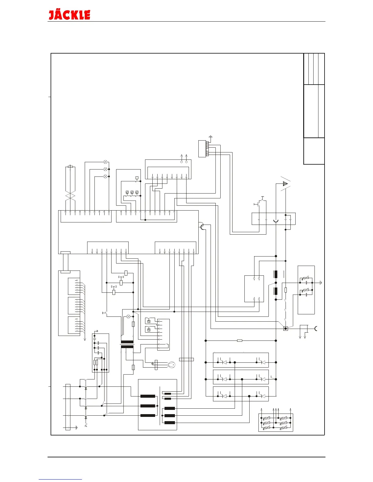
SGR2 AN.2
PS0-070.030
circuit diagram
PLASMA 70 S
Date:
No.:
prim.control transf. fuse,
control transf. fuse,
mains control lamp
temperature indicatorfault
compressed air fault indic.
torch fault indicator
pilot contactor
smoothing choke
HF blocking choke, PLD 1
HF blocking choke, PLD 10
current transformer
HF filter
current
former
L4
trans-
current
control
board
current flow
torch trigger
voltage
control boarddriving boardA2
flat
strip
A1,A3,...
G1,G2,...
K1,K2,...
thyristor
protection unit
thyristor strands
red
white
blue
current trans-
former board A3
workpiece connection HF protection board
central connection torch
Hall
transformer
terminal
E
A
UU
1000V
0,1µF
A5
S20
K275
HFS 1
11.12.96
Q1
R1
master switch
pilot resistor 3 Ohm
R2
R3
S1
S2
S3,S4
S5
S6
S7
S8
S9
10 k lin.
170° C
90° C
50° C
resistor 250 Ohm / 100 W
potentiometer
torch trigger
torch safety switch
transf. thermosw.
thyristor thermosw.
80° C
thyristor thermosw.
transf. thermoswitch
compressed air test key
manometric switch / air
S225-647859
M1 fan
T 2 A
1µF
109876531
VR 1
S6 S7
T 2 A
M
1
blue
black
brown
M1
fan control p.c.b.
A7
regul. of cutting current
3U
3V
A
E
A
E
T1
T2
V1,V2,V3
Y1
Y2
control transformer
thyristor modules
solen. valve, low air flow
high air flowsolen. valve,
cutting transformer
00
H
H
B
T
T
24
SIG 3.2
ignition unit
A5
0,68µF
X2
250V~
47R
9W14
16
6
2
12
A6 interference filter
J Ä C K L E