EasyManua.ls Logo

Jackson Systems Comfort System Z-300-HC - User Manual

Jackson Systems Comfort System Z-300-HC
2 pages
Print Icon
To Next Page IconTo Next Page
Loading...
Zone Control Made Simple™
5418 Elmwood Avenue, Indianapolis, IN 46203-6025
Toll Free: 888.652.9663 Fax: 317.227.1034
www.jacksonsystems.com
Comfort System
Installation Instructions for Z-300-HC Zone Control Panel
Heat / Cool Auto Changeover - Cooling Priority
Installation Notes:
Connect only 24 Vac to Control
Panel.
Zone dampers are powered
closed / spring return open.
Specifications:
Terminal Designations:
To install the panel, first slide the PC
board out of its base and screw the
base to a flat surface next to the
HVAC equipment. The PC board
should be reinstalled by centering it
over the base and pushing firmly.
The control panel requires a
separate 24 Volt transformer.
No special wire is required.
The thermostat and motorized
dampers may be located up to 300
feet from the control panel when
using 18 gauge thermostat wire.
The left fuse (4 Amp) protects the
relay contacts. The right fuse (4
Amp) protects the printed circuit
board.
If condensing unit is not equipped
with short cycle protection timer,
(TD-5) should be installed.
The two wires from the condensing
unit should be connected to the ‘Y’
and transformer common terminals
at the furnace.
The low limit (FS-38) should be
wired to the ‘LL terminals on the
panel (remove jumper). The
compressor will shut off when low
limit trips out.
The high limit (HL-170) should be
wired to the ‘HL terminals on the
panel (remove jumper). The furnace
will shut off when high limit trips out.
A 40 VA transformer will power the
panel and up to four (4) dampers.
A 75 VA transformer will power the
panel and up to seven (7) dampers.
Up to three (3) dampers can be
connected in parallel. A total of no
more than seven (7) dampers may
be connected to the system. A
system may be a single panel or
multiple panels.
If more than three (3) zones are
required, two additional panels can
be used to control up to a total of
nine (9) zones. T5 terminal strip is
used only when more than three
zones are required.
Label the dampers, damper wires
and thermostat wires with the zone
number and the area they serve.
Panel Dimensions:
Height: 5.0 inches
Width: 10.0 inches
Depth: 2.0 inches
Mounting:
2 back plate screws
OperatingAmbient Temperature:
-20° to 160° F
Power Supply:
24 Vac 40VA/ 75 VAtransformer
W = Heat
Y = Cool
G = Fan
R = Hot 24 Volt
X = Common
D = Damper
LL = Freeze Stat
HL = High Limit
H = Hot 24 Volt
X = Ground or Common
ZONE 1
ZONE 2
ZONE 3
CONTACTS
4 AMP FUSES
PC BOARD
COOLING
PRIORITY
POWER
HEAT
COOL
FAN
ZONE 1
CALLING
ZONE 2
CALLING
ZONE 3
CALLING
HVAC UNIT
WYG RXDD
WYG RXDD
WYG RXDD
4 AMP
WYG R HXLL LL HL HL
T5
Comfort System™
Z-300-HC
PATENTED 5,944,098
4 AMP
WYG RC
WYG RC
D
SINGLE STAGE
HEAT / COOL
THERMOSTAT
DAMPER MOTOR
0.36 AMPS 10 VA
HVAC UNIT
TERMINAL
STRIP
LOW
LIMIT
HIGH
LIMIT
120/24 VAC
TRANSFORMER
HXW Y G R LL LL HL HL
DD
WYG RX
WIRE THE SAME
AS ZONE 1
FAN LED INDICATES
WHEN A
THERMOSTAT IS
CALLING FOR FAN.
WHEN GREEN ZONE
LEDS ARE ON, THOSE
ZONES ARE CALLING
FOR HEATING OR COOLING
123456
JUMPERS
TM
Question and Answer IconNeed help?

Do you have a question about the Jackson Systems Comfort System Z-300-HC and is the answer not in the manual?

Summary

Installation Notes

Control Panel Installation

Slide PC board out, screw base to surface, center and firmly push board back onto base.

Power Supply Connection

Connect only 24 Vac to the control panel using a separate 24 Volt transformer.

Wiring Considerations

Use 18-gauge wire for thermostats/dampers up to 300 feet from panel.

Fuse Protection

Left fuse protects relay contacts; right fuse protects the printed circuit board.

Zone Damper Operation

Zone dampers are powered closed and spring return open.

Specifications

Panel Dimensions

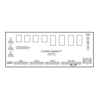
Height: 5.0 inches, Width: 10.0 inches, Depth: 2.0 inches.

Mounting

Mounts using two back plate screws.

Operating Ambient Temperature

Operates between -20° to 160° F.

Power Supply Requirements

Requires 24 Vac transformer, 40VA or 75 VA.

Terminal Designations

HVAC Unit Terminals

Defines terminals for Heat (W), Cool (Y), Fan (G), Hot 24V (R), Common (X).

Damper and Limit Terminals

Defines terminals for Damper (D), Freeze Stat (LL), High Limit (HL), Hot 24V (H), Common (X).

Sequence of Operation

Zone Control System Function

Controls multiple zones from a single HVAC unit, dampers close for non-calling zones.

Auto Changeover - Cooling Priority

Prioritizes cooling if zones call for both heating and cooling simultaneously.

Thermostats

System Checkout

Wiring Verification

Ensure all wires are connected securely to the proper terminals.

Limit Control Wiring Check

Verify low limit (FS-38) to 'LL' and high limit (HL-170) to 'HL' terminals.

Damper Operation Test

Check zone dampers are powered closed and spring return open.

Heating;Cooling Call Test

Test system by calling for heat/cooling to verify proper damper states.

Jackson Systems Comfort System Z-300-HC Specifications

General IconGeneral
ModelZ-300-HC
CategoryControl Panel
Zones SupportedUp to 3 Zones
Input Voltage24 VAC
Output Voltage24 VAC
TypeHVAC Control Panel
CompatibilityCompatible with most HVAC systems
Operating Temperature32°F to 122°F (0°C to 50°C)
Humidity Range5% to 95% RH non-condensing
Weight1.2 lbs

Related product manuals