60
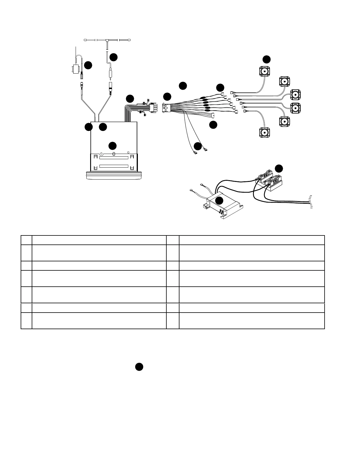
II. Aquatic stereo diagram
B. Testing power to stereo
1. Set voltage meter to 750 VAC.
2. Test across the TB1 terminal block (
J
) for 230 VAC.
3. If voltage is present, proceed to step C. If no voltage is present, check the breaker.
C
I
E
B
J
M
L
K
H
D
A
F
G
N
A Aquatic stereo with connections H Spade connectors (connect to the power supply)
B
Remote sensor connection (connects to
remote sensor unit)
I Power supply (located in equipment bay)
C Antenna connection on stereo J TB1 terminal (located in control box)
D
Stereo harness (connects to wiring harness
“E”)
K Spa speakers (connect to wiring harness)
E
Spa wiring harness (connects spa compo-
nents to stereo)
L Wireless remote sensor unit
F Spa harness speaker connectors M Stereo antenna
G
Subwoofer connector (connects to spa wiring
harness)
N Crossovers for the speakers
 Loading...