EasyManua.ls Logo

Jaeger 21010508J User Manual

Default Icon
14 pages
To Next Page IconTo Next Page
Page #1 background imageLoading...
Page #1 background image
Einbauanleitung
Fitting instructions
Instructions de montage
Istruzione di montaggio
Instrucciones de montaje
Elektro-Einbausatz für Anhängerkupplung / 13-polig / 12 Volt / ISO 11446
Faisceau électrique pour crochet d’attelage / 13 broches / 12 Volt / ISO 11446
Electric wiring kit for towbars / 13-pin / 12 Volt / ISO 11446
Cablaggio elettrico per ganci di traino / 13 poli / 12 Volt / ISO 11446
Kits eléctricos para enganches de remolques / 13 pins / 12 Volt / ISO 11446
Montagehandleiding
Elektro-inbouwset voor aanhangerkoppeling / 13-polig / 12 Volt / ISO 11446
AUDI
No. 21010508J
87010574 / 15.11.2012 / Seite 1/14 / © JAEGER automotive GmbH / Chromstrasse 90 / D-33415 Verl / FON: +49 5246-9210-0 / FAX: +49 5246-9210-20 /e-mail: info@jaeger-automotive.de
A6 Avant 03/05 08/11
A6 Limousine 05/04 02/11
A6 Saloon 05/04 02/11
A6 Allroad Quattro 05/06 04/12
Question and Answer IconNeed help?

Do you have a question about the Jaeger 21010508J and is the answer not in the manual?

Jaeger 21010508J Specifications

General IconGeneral
BrandJaeger
Model21010508J
CategoryAutomobile Accessories
LanguageEnglish

Summary

Audi A6 Trailer Wiring Kit

Important Safety and Installation Guidelines

Professional Installation and Warranty

Emphasizes qualified installation and potential warranty voidance.

Operational Notes and Diagnostic Limitations

Covers adapter removal, manufacturer modifications, and diagnostic module limitations.

Wiring Kit Components and Vehicle Integration

Component Identification and Quantity

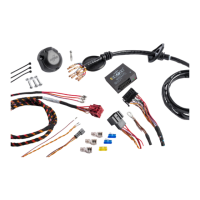
Diagrams illustrating the wiring kit components and their quantities.

Installation Location Overview

Visual guide showing where the wiring kit is installed on the vehicle.

Critical Safety Precautions

Battery Disconnection Procedure

Mandatory steps for disconnecting the vehicle battery before commencing work.

Initial Installation Steps (1-5)

Visual guide for the first five installation steps of the wiring kit.

Trailer Socket Standards and Wire Identification

ISO 11446 Socket Configuration

Details pin assignments and maximum power output for the trailer socket.

Multilingual Wire Color Code

Provides wire color translations across multiple languages for identification.

Intermediate Installation Steps (6-11)

Visual guide for installation steps 6 through 11.

Installation Steps and Connection Variations

Installation Steps (12-14)

Visual guide for installation steps 12 through 14.

B+/30 Connection Bolt Availability

Guides installation based on the presence or absence of a B+/30 connection bolt.

Advanced Wiring and Data Connections

Installation Steps (15-17)

Visual guide for installation steps 15 through 17.

CAN-Data Wire Connection Details

Specific instructions for connecting the CAN-Data wire.

Specific Connections and Optional Components

Installation Steps (18-22)

Visual guide for installation steps 18 through 22, including optional parts.

Optional Part and Manual Storage

Information on an optional part and advice on storing the manual.

Trailer Functionality and Setup Procedures

Installation Steps (23-28)

Visual guide for installation steps 23 through 28.

Trailer Light Functions and Adapter Sockets

Details trailer light functions, setup, and adapter socket options.

Vehicle Configuration for Trailer Operation

Control Unit Coding Across Languages

Guides for configuring vehicle control units for trailer operation in multiple languages.

Detailed Vehicle Coding Procedures

ESP Control Unit Coding

Specific steps for coding the ESP control unit for trailer mode.

Ride-Control and Parking Aid Coding

Coding procedures for vehicles with ride-control and parking aid systems.

Data Bus Interface Coding

Instructions for coding the data bus interface for trailer function.

Vehicle System Configuration Details

Italian and Dutch Configuration Steps

Configuration steps for Italian and Dutch language vehicle systems.

Spanish Configuration Steps

Configuration steps for Spanish language vehicle systems.

Diagnostic Functions and Lamp Compensation

Control LED Diagnostic Functions

Explains how to diagnose control LEDs for trailer functions.

Trailer Indicator Lamp Substitution

Details how trailer indicator failures are compensated by rear lights.

Symbol Explanation Guide

Related product manuals