OPERATION AND MAINTENANCE MANUAL
12-2015
3
1 TECHNICAL DESCRIPTION
1.1 PRODUCT NAME AND FEATURES
The purpose of this TED are air valves for water systems.
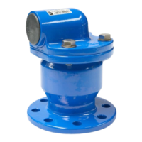
TYPE 7010
-single step cast iron air valve for water systems, flanged
- with a floating ball (closing device) vulcanised in 100% with an elastomer
- with an o-ring cover gasket
- with screws which connect the cover with the body.
TYPE 7040
-single step brass air valve for water systems, threaded
- stainless steel with a floating ball
- with an o-ring cover gasket
TYPE 7050
- two step air valve for water systems which comprises
valves 7010 and 7040.
1.2 PURPOSE
Flanged cast iron and brass threaded air valves are intended to deaerate the pipe system when
it is filled with water or to aerate the pipe system when it is emptied in potable water systems and
industrial systems. They can be used in above ground and underground systems, essentially in the
highest point of horizontally placed piping.
1.3 TECHNICAL SPECIFICATION
Cast iron air valves TYPE 7010 are intended for purposes of aerating and deaerating systems
for potable water and other liquids (obtain agreement from the producer):
- operation temperature ranges from -10°C to +70°C.
- range of used diameters (dimensions): - DN50 –DN200[mm];
- max flow speed of medium - liquid up to 4[m/s];
- gas up to 15[m/s];
- nominal pressure value: - PN: - 1,6 MPa;
- operational pressure range: - 0,02 – 1,6MPa;
Flanges at valves TYPE 7010 are made according to PN-EN 1092-2 1999 with dimensions
appropriate to the assumed nominal pressures.
Dimensions of flanged air valves TYPE 7010 comply with the technical documentation.
Choice of TYPE 7010 valves is carried out regarding the amount of supplied (returned) air,
which involves the pipeline diameter and the length of the deaerated section. When filling the
pipeline, maximum flow speed in an unobstructed cross-section should not exceed 20 m/s, so that
the ball is not carried away and the flow is not closed before the deaerating process is finished.
When filling the pipeline, the whole of deaerating cross-section of a valve is available.