5
Attenzione:
A causa di un dispositivo di sicurezza supplementare devono essere tutti quattro in-
teruttori del trasmittente in posizione OFF quando si accende il trasmittente. In caso
contrario, verrà visualizzato un avviso e un allarme acustico no a quando tutti gli
interruttori sono nella posizione corretta.
Warning:
For your safely, the 4 switches of the transmitter must be in their „o“ postition and
throttle stick must be the lowest position when turning the transmitter on. If not, a war-
ning screen will be displayed until all switches are in the right position.
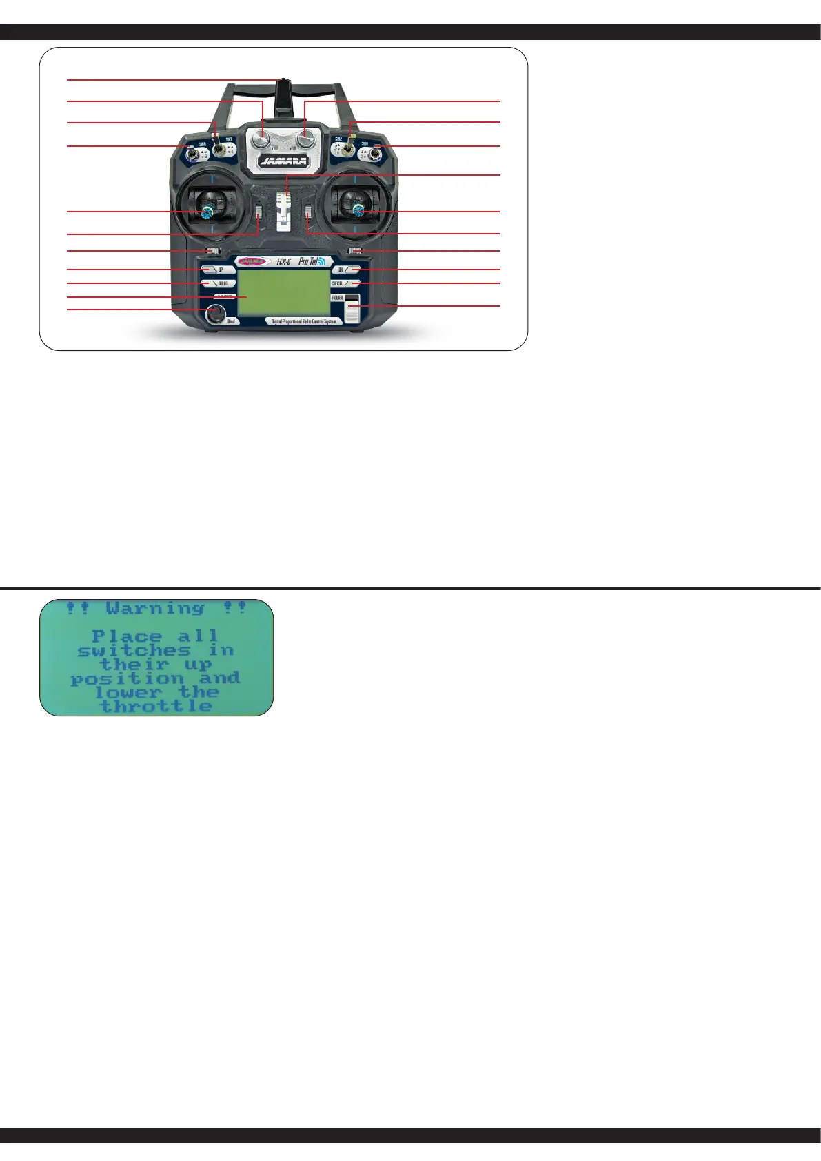
IT - Descripción gas destra
Antenna 2,4 GHz
2 Girare regolatoreVRB (Programmazione libera)
3 Interrutore B (Programmazione libera)
4 InterrutoreA (Programmazione libera)
5 Modo 1 = Stick elevator/direzionale
Modo 3 = Stick elevator/aileron
6 Elevator trim
7 Modo 1 = Aileron trim
Modo 3 = Direzionale trim
8 Pulsante UP
9 Pulsante DOWN
10 LCD
11 Tasto di collegamento
12 Girare regolatore VAA (Programmazione libera)
13 Interrutore C (Programmazione libera)
14 Interrutore D (Programmazione libera)
15 Aggancion cinghia
16 Modo 1 = Stick gas/aileron
Modo 3 = Stick gas/direzoinale
17 Gas trim
18 Modo 1 = Direzionale trim
Modo 3 = Aileron trim
19 Invio (ENTER)
20 Exit / indietro
21 Interruttore on/o
GB - Denition of key funktions throttle right
1 2,4 GHz Antenna
2 Rotary poteniometer VRB (free programmable)
3 Switch B (free programmable)
4 Switch A (free programmable)
5 Mode 1 = Elevator/Rudder stick
Mode 3 = Elevator/Aileron stick
6 Elevator Trim
7 Mode 1 = Aileron Trim
Mode 3 = Rudder Trim
8 Key up
9 Key down
10 LCD Display
11 Bonding button
12 Rotary poteniometer VAA (free programmable)
13 Switch C (free programmable)
14 Switch D (free programmable)
15 Hook
16 Mode 1 = Throttle/Aileron stick
Mode 3 = Throttle/Rudder stick
17 Throttle Trim
18 Mode 1 = Rudder Trim
Mode 3 = Aileron Trim
19 Enter button
20 Exit / Back button
21 Power switch
1
11
12
13
14
15
16
17
18
19
20
2
3
4
5
6
7
8
9
10
21

 Loading...