3
DE - Montage | GB - Assembly | FR - Assemblage | IT - Montaggio | ES - Montaje
DE
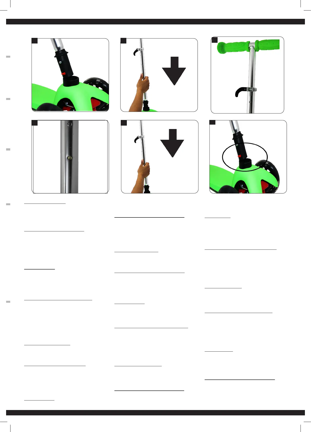
1. und 2. Montage des Rollers
• Stecken Sie die silberfarbene Stange (Abb. 1+2) mit der
Unterseite in das Loch am vorderen Ende des Trittbretts
ein.
• Achten Sie auf das Klickgeräusch, wenn die
Lenkstange eingerastet ist. Überprüfen Sie den festen
Sitz der Lenkstange.
3. und 4. Höhenverstellung der Lenkstange
• ÖnenSiedenschwarzenHebel(Abb. 3).
• Drücken Sie die eingerastete Kugel (Abb.4) und
schieben Sie den Lenker in die gewünschte Position
(eines der drei Löcher) (Abb.4).
• Schließen Sie den schwarzen Hebel wieder.
Achten Sie bitte darauf, dass sich der Hebel nicht zu
leicht schließen lässt: Ziehen Sie gegebenenfalls die
gerielteSchraubeetwasnach,fallssichderHebelzu
leicht, bzw. zu schwer schließen lässt.
Lenken und Bremsen:
• Durch Bewegung der Lenkstange werden die Vorderräder
des Rollers mechanisch in die entsprechende Richtung
gelenkt.
• Durch Betätigung der Rücktrittsbremse kann der Roller
gebremst werden.
Achtung! Bitte nicht über 5 km/h fahren, die Bremse ist nur
bis zu dieser Geschwindigkeit ausgelegt.
5. und 6. Demontage des Rollers zum Transport:
• Zum Transport des Rollers kann die Lenkstange
demontiert werden (Abb.5) Drehen Sie hierfür den
Roller mit dem Lenker nach unten. An der Vorderseite
mitdenzweiRädernisteineroteKunststonase
(Abb. 6) zu sehen.
• Drücken Sie diese und ziehen Sie den Lenker mit einer
kräftigen Bewegung heraus. Sollte das nicht funktionie
ren,empfehlenwirdieZuhilfenahmeeinesachen
Schraubendrehers.
Achtung, Verletzungsgefahr!
GB
1. and 2. assembly of the scooter
• Insert the silver coloured bar (g. 1+2) with the undersi
de into the hole at the front end of the running board.
• Pay attention to the clicking noise when the handlebar is
xedinplace.CheckthexedSeatofthehandlebar.
3. and 4. height adjustment of the handlebar
• Open the black lever (Fig. 3).
• Press the anchored ball (Fig.4) and Push the handle
bars into the desired position. (one of the three holes)
(Fig.4).
• Close the black lever again. Make sure that the lever
can not be closed too easily: If necessary, pull the
screw slightly; in case the lever should become too tight
– ease it a little.
Steering and braking:
• By moving the handlebars, the front wheels are mecha
nically steered in the desired direction.
• By standing on the back foot brake, the scooter can be
braked.
Attention! Please do not drive over 5 km/h, the brake is only
designed up to this speed.
5. and 6. Disassembly of the scooter for transport:
• To transport the scooter, the handlebar can be removed
(Fig.5) Turn the scooter with the handlebar downwards.
At the front of the two wheels you can see a red plastic
nose (g. 6).
• Push it and pull out the handlebars with a strong
movement. If this does not work, we recommend using
aatscrewdriver.Attention,dangerofinjury!
FR
1. et 2. Montage de la trottinette
• Insérezlabarreargentée(Fig. 1+2)avecsafaceinférieure
dansletrouàl‘extrémitéavantdumarchepied.
• Faitesattentionaubruitdecliquetislorsqueleguidonest
engagé.Vériezqueleguidonsoitbienmisenplace.
3. et 4. Réglage en hauteur de la barre de direction
• Ouvrez le levier noir (Fig. 3).
•Poussezlabouleverrouillée(Fig.4) et faites glisser le
guidondanslapositionsouhaitée(l‘undestroistrous)
(Fig.4).
• Refermez le levier noir en prenant soin de ne pas le refer
mertropfacilement:Sinécessaire,serrerlégèrementlavis
àailettessilelevieresttropfacileoutropdicileàfermer.
Direction et freinage :
• Endéplaçantleguidon,lesrouesavantdelatrottinette
sontdirigéesmécaniquementdansladirectionappropriée.
•Latrottinettepeutêtrefreinéenactionnantlefreinderecul.
Attention ! Ne dépassez pas 5 km/h, le frein n‘est conçu
que pour cette vitesse.
5. et 6. démontage de la trottinette pour le transport :
•Pourtransporterlatrottinette,leguidonpeutêtreretiré
(Fig.5) Tournez la trottinette avec le guidon vers le bas.
A l‘avant, avec les deux roues, vous pouvez voir un nez en
plastiquerouge(g. 6).
• Poussez-le et sortez le guidon d‘un mouvement puissant.
Si cela ne fonctionne pas, nous vous recommandons
d‘utiliser un tournevis plat.
Attention,risquedeblessure!
IT
1. e 2. Montaggio del monopattino
• Inserire la barra color argento (Figg. 1+2) con la sua parte
inferiorenelforoall‘estremitàanterioredellapartepiana.
• Prestareattenzionealrumoredelclicquandoilmanubrio
èinnestato.Controllarecheilmanubriosiassato
saldamente.
3. e 4. Regolazione in altezza dell‘asta dello sterzo
• Aprire la leva nera (Fig. 3).
• Premere la sfera innestata (Fig.4) e far scorrere il manubrio
nella posizione desiderata (uno dei tre fori) (Fig.4).
• Chiudere di nuovo la leva nera.
Assicurarsi che la leva non possa essere chiusa troppo
facilmente: se necessario, serrare leggermente la vite a
costeselalevaètroppofacileotroppodicileda
chiudere.
Sterzare e frenare:
• Muovendo il manubrio, le ruote anteriori del monopattino
vengono indirizzate meccanicamente nella direzione
appropriata.
• Azionando il freno, il monopattino può frenare.
Attenzione! Si prega di non superare i 5 km/h, il freno è
progettato solo per questa velocità.
5. e 6. Smontaggio del monopattino per il trasporto:
• Per trasportare il monopattino, il manubrio può essere
smontato (Fig.5) Ruotare il monopattino con il manubrio
verso il basso. Nella parte anteriore con le due ruote è
presente un naso di plastica rossa (Fig. 6).
• Spingerlo ed estrarre il manubrio con un movimento de
ciso.Sequestonondovessefunzionare,siconsigliadi
utilizzare un cacciavite a testa piatta.
Attenzione, pericolo di lesioni!
ES
1. y 2. Montaje del patinete
• Introducir la barra plateada (Figs. 1+2) con la parte
inferioreneloriciodelapartedelanteradelaparte
plana.
• Preste atención al sonido cuando el manillar está engan
chado.Compruebequeelmanillarestébiensujeto.
3. y 4. Ajuste de la altura de la barra de dirección
• Abrir la palanca negra (Fig. 3).
•Empujelabolabloqueada(Fig.4) y deslice el manillar
hasta la posición deseada (uno de los tres agujeros)
(Fig.4).
• Vuelvaacerrarlapalancanegra.Asegúresedeque
la palanca no se pueda cerrar con demasiada facilidad:
Si es necesario, apriete ligeramente el tornillo estriado si
lapalancaesdemasiadofácilodemasiadodifícilde
cerrar.
Dirección y frenado:
• Al mover el manillar, las ruedas delanteras del patinete
se dirigen mecánicamente en la dirección adecuada.
• El patinete puede ser frenado accionando el freno de
retroceso.
Atención! Por favor, no conduzca a más de 5 km/h, el freno
sólo está diseñado para esta velocidad.
5. y 6. Desmontaje del patinete para su transporte:
•Paratransportarelpatinete,sepuedequitarelmanillar
(Fig.5) Gire el patinete con el manillar hacia abajo. En
la parte delantera con las dos ruedas se puede ver una
nariz de plástico roja (g. 6).
•Empújaloytiradelmanillarconunmovimientofuerte.
Si esto no funciona, recomendamos usar un destornil
lador plano.
Atención, peligro de lesiones!
1 2
54
3
6


 To Next Page
 Loading...