Page 9
ENGLISH
Jandy
®
AquaLink
®
TCX™ Power Center
|
Installation & Operation Manual
Jandy
®
AquaLink
®
TCX™ Power Center
|
Installation & Operation Manual
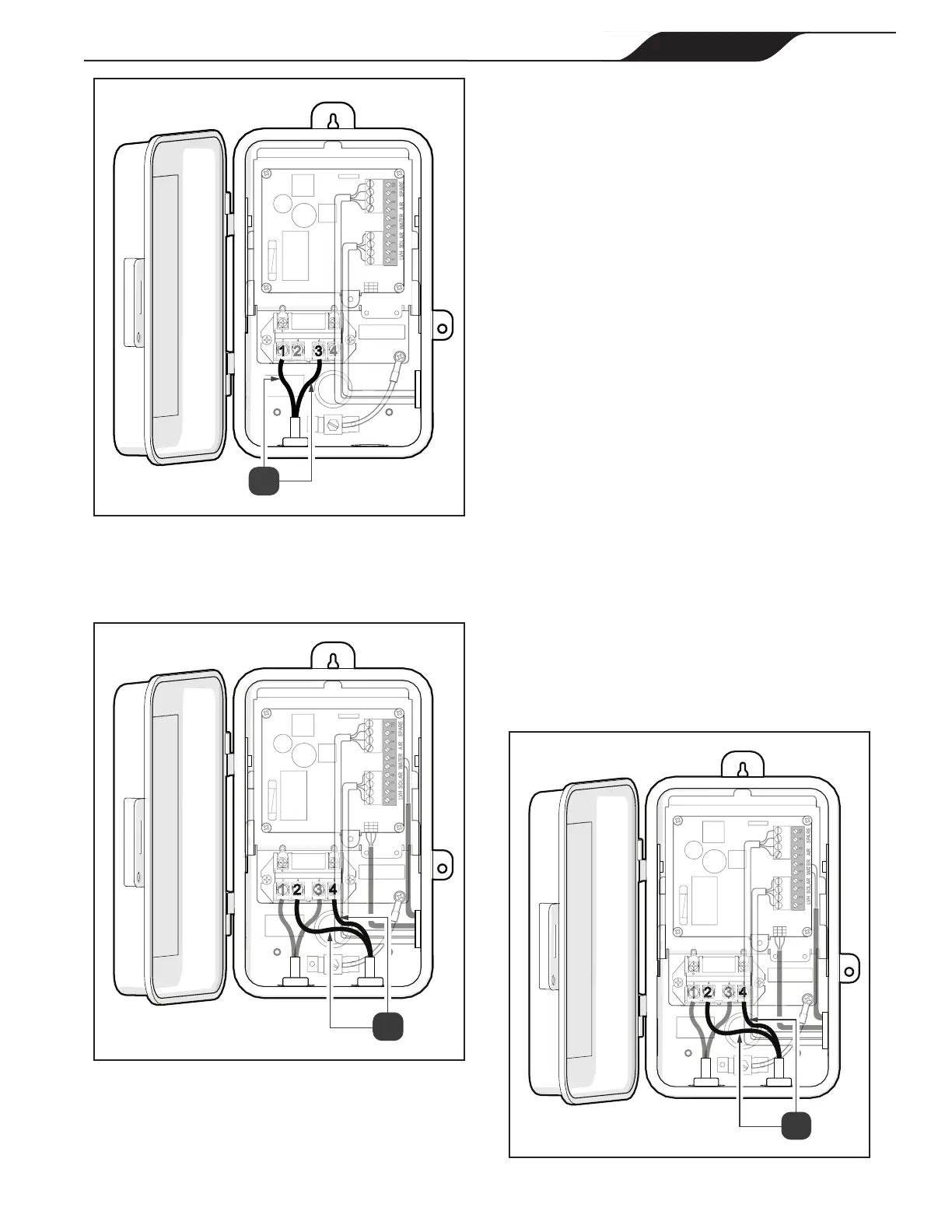
1 2 3 4 5 6 7 8 9 10
LVH SOLAR WATER AIR SPARE
Figure 2. Connect Input Cables
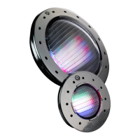
10. Connect single speed lter pump to load side of
relay, use terminals 2 and 4, see Figure 3 (a).
1 2 3 4 5 6 7 8 9 10
LVH SOLAR WATER AIR SPARE
Figure 3. Connect Load Input Cables
3.2.2 High Voltage Wiring (Variable Speed Pumps)
NOTE: The variable speed pump must be wired “hot”.
1. Turn o power at the breaker panel.
2. Remove two of the knockouts from the enclosure.
One knockout will lead to the breaker panel and the
other will lead to the pool equipment.
3. If relay is not to be used for a Saltwater
Chlorinator, connect Equipment (Lighting/
Water Feature Pump/Booster Pump/Solar Pump).
Measure the distance from the equipment to the
enclosure.
4. If relay will be used for Saltwater Chlorinator, pull
lines from Filter Pump breaker to line side of relay
and wire pump on line side of the relay. Wire the
Saltwater Chlorinator to load side.
5. Cut a piece of 1/2ʺ electrical conduit to match this
distance.
6. Feed the cables from the equipment through the
conduit and into the AquaLink
TCX enclosure.
7. Press the conduit into the terminal adapter.
8. Connect the ground wire to the green screw located
on the AquaLink TCX chassis. The ground wire
will be green/yellow.
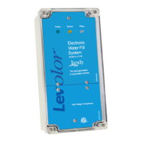
9. Connect one “Load” input to Terminal 2 and the
other to Terminal 4, see Figure 4 (a).
1 2 3 4 5 6 7 8 9 10
LVH SOLAR WATER AIR SPARE
Figure 4. Connect Load Input Cables