Page 5
NOTE Refer to Figure 5 for Steps 6 and 7.
6. (Jandy DEL, DEV, and JS series Filters) Plumb
the Slide Valve outlet labeled
PORT A
to the heater
or pool return lines.
(Other Manufacturers Filters with the lter top
port as the inlet) Plumb the Slide Valve outlet
labeled
PORT E
to the heater or pool return lines.
7. (Jandy DEL, DEV, and JS series Filters) Plumb
the Slide Valve outlet labeled
PORT E
to the waste
line as needed.
(Other Manufacturers Filters with the lter top
port as the inlet) Plumb the Slide Valve outlet
labeled
PORT A
to the waste line as needed.
8. Allow the connections to dry for 24 hours.
9. When the glue is dry, start the system and check
for proper water ow.
Section 3. Normal Operation
WARNING
NEVER attempt to assemble,
disassemble or adjust the lter when
there is pressurized air in the system.
Starting the pump while there is
any pressurized air in the system
can cause the lter lid to be blown
off, which can cause death, serious
personal injury or property damage.
1. Turn off the system pump(s).
2. Open the air release valve on top of the lter tank
to release all pressure from inside the tank and
system. Wait for all the air to evacuate the system.
3. (Jandy DEL, DEV, and JS series Filters) Ensure
that the Slide Valve handle is fully depressed
(handle and piston pushed all the way down). Turn
the handle until the stainless steel pin on the piston
locks into the position bracket.
(Other Manufacturers Filters with the lter
top port as the inlet) Ensure that the Slide Valve
handle is fully extended (handle pulled all the way
up).
4. Turn on the lter pump(s). Check the system for
normal water ow.
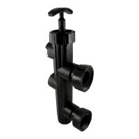
Figure 6. SVLV2 Plumbing Conguration for
Other Manufacturers Filters with Inlet at
Top Port - Filtration Mode
Handle Pulled Up
To Pool
(PORT A)
From Pump
(PORT B)
Filter Outlet
(PORT C)
Filter Inlet
(PORT D)
To Waste
(PORT E)
Figure 5. SVLV2 Plumbing Conguration for
DEL, DEV and JS Series Filters -
Filtration Mode
Handle Pushed
Down
CAUTION
To avoid costly equipment damage, after verifying
proper water flow and prior to putting system into
normal operating conditions, flush the system using
Backwash mode until the waste water is clean.
Refer to Section 4 for Backwash mode operation
instructions.
To Waste
(PORT A)
From Pump
(PORT B)
Filter Inlet
(PORT C)
Filter Outlet
(PORT D)
To Pool
(PORT E)