Z-Wave 45709, 45712 or 45715
1.Shut off power to the circuit at fuse box or circuit breaker.
2. Remove wall plate.
! Warning: Verify power is OFF to switch box before
continuing.
3. Remove the switch mounting screws.
4. Carefully remove the switch from the switch box. DO
NOT disconnect the wires.
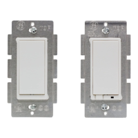
5. There are ve wiring connections on the Z-Wave
dimmer and switch; these are marked LINE (Hot),
NEUTRAL, LOAD, GROUND and TRAVELER. The
Traveler terminal is only used for 3-way, 4-way or
5-way wiring and should be insulated if the dimmer/
switch is being installed in a single pole, 2-way
system (one switch & one load). Match these leads
or screw terminals to the wires connected to the existing
switch.
6. Disconnect the wires from the existing switch.
7. Connect the green or bare copper ground wire to the
GROUND lead or terminal. Use 12AWG or larger wires
suitable for at least 176ºF(80ºC).
8. Connect the white wire to the lead or terminal marked
NEUTRAL. (The 45715 does not have a connection to
Neutral)
9. Connect the black wire that goes to the light to the lead
or terminal marked LOAD. Use 14AWG or larger wires
suitable for at least 176ºF(80ºC).
10. Connect the black wire that comes from the electrical
 Loading...