103721 Rev. E
7
ENGLISH
INSTALLATION
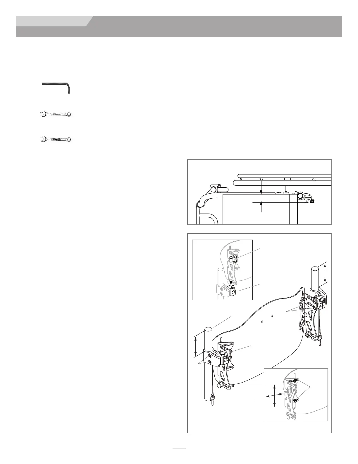
ATTACHING FOUR POINT HARDWARE
(OPTIONAL) (FIG. 7, 8, 9)
Tools required (included with J3 Back with 4-Point
Hardware)
• 4mm hex key
• 10mm box end wrench
• 5/8" box end wrench
Installing the 4-Point Hardware
1. Loosen the clamp screws (A) with the supplied 4mm hex key
and slip the clamps around the Back Canes (B).
2. The mounting hardware should be at equal heights on each
back post (Fig. 8) and parallel to the seat frame (Fig. 7).
3. Hand tighten clamp screws (A). Loosen bracket nuts (C) and
Mounting Pin bolts (F) using the supplied 10mm box-end
wrench until hardware can move easily in all directions
NOTE– For large tube diameters, clamp screws may have to be removed
completely.
4. Attach the J3 Back by inserting left and right Mounting Pins
(D) in the left and right Latch Receivers (E).
5. Install back to the approximate location, relative to both
chair and user.
6. Tighten bolts on the inside of the Mounting Pin (F). Torque
to 100 - 110 in-lbs.(11.3 - 12.4 Nm).
NOTE– Receivers may require additional lateral adjustment to ensure proper
alignment.
7. Tighten bracket nuts (C). Torque to 75 - 85 in-lbs. (8.5 - 9.3
Nm).
NOTE– Back height may require additional adjustment to ensure proper fit
to the user.
8. Test back release by pressing the release levers (L) forward
and removing the back off the chair. Proper alignment of the
mounting hardware and back is achieved when smooth
attachment and release can be easily done.
9. If proper alignment has not been achieved, adjust the com-
ponents until properly aligned.
10. Once properly aligned, tighten the hardware receiver clamp
screws (A). Torque to 75 - 85 in-lbs (8.5 - 9.3 Nm)
11. Loosen bolts (G) to install Lower Receivers on Back Canes
(H).
12. Use a 5/8" end wrench to loose the nut (K) that secures the
Lower Mounting Pin (I) so that it slides fore and aft.
13. Slide lower receiver up (J) until it surrounds the Lower
Mounting Pin (I).
NOTE– Leave 1/8" to 1/4" of space between the bottom of the Lower
Mounting Pin (I) and the bottom of the Lower Receiver Channel (J).
NOTE– Make sure the Upper Mounting Bracket and Lower Receiver Bracket
are in alignment on the Back Canes. Misalignment of the brackets
may result in impaired function of quick-release.
14. Once properly aligned, tighten the hardware receiver clamp
screws (G). The recommended torque specification is 75 -
85 in-lbs (8.5 - 9.3 Nm). Then tighten the Lower Mounting
Pin nut (K). Torque to 100 - 110 in-lbs.(11.3 - 12.4 Nm).
Figure 7
Figure 8
E
L
C
A
B
F
D