Do you have a question about the JB Systems VX700 and is the answer not in the manual?
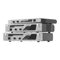
Lists the professional features of the JB Systems amplifier, including protection, cooling, input types, and output connectors.
Details the items to check in the carton before operating the JB Systems amplifier.
Provides essential safety warnings regarding electric shock, moisture, ventilation, and unit maintenance.
Instructions for safely cleaning the amplifier, emphasizing water use and avoiding volatile liquids.
Guidance on connecting signal inputs and speaker outputs using recommended cables and connectors.
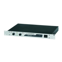
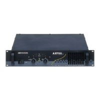
Explains the function of the power LED, mains switch, and gain controls for input sensitivity adjustment.
Describes the meaning of the CLIP LED (output distortion) and PROTECT LED (system protection).
Details the BRIDGE and PARALLEL mode LEDs and their implications for amplifier operation.
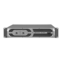
Emphasizes the importance of ventilation holes for preventing overheating during operation.
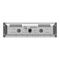
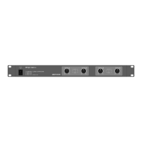
Details the Speakon and binding post speaker outputs, including wiring and usage recommendations.
Explains the Ground Lift switch for hum reduction and the MODE switch for stereo, bridge, or parallel operation.
Illustrates how to connect speaker cabinets for stereo, bridge, and parallel modes using rear panel switches.
| Amplifier type | Class AB |
|---|---|
| Frequency response | 20Hz - 20kHz |
| Input sensitivity | 0.775V |
| Dimensions | 482 x 88 x 314 mm |
| Weight | 7.2 kg |
| Impedance | 4 - 8 ohms |
| Input impedance | 10k ohms |
| Protection | Thermal, short circuit, DC protection |