LOUDSPEAKER
SYSTEM
PROGRAM
SOURCE
TWO
AMPLIFIERS
ACTIVE
FREQUENCY
DIVIDING
NETWORK
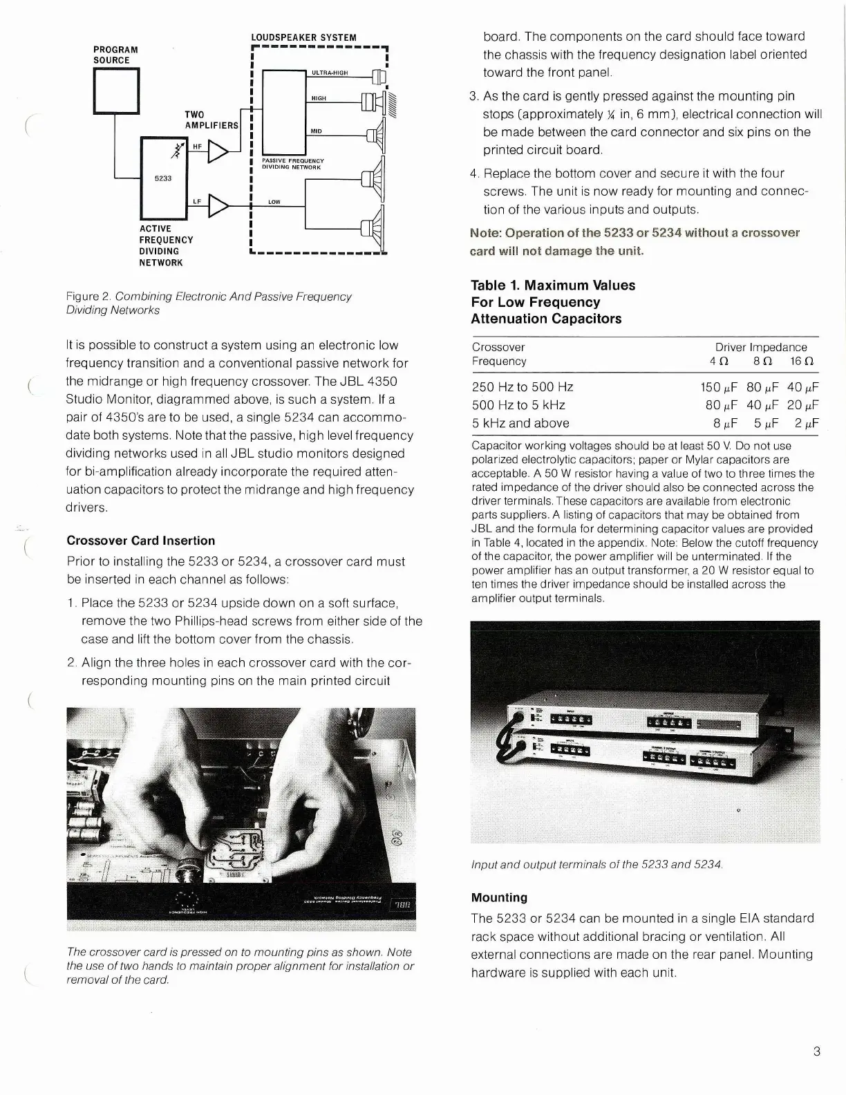
It is possible to construct a system using an electronic low
frequency transition and a conventional passive network for
the midrange or high frequency crossover. The JBL 4350
Studio Monitor, diagrammed above, is such a system. If a
pair of 4350's are to be used, a single 5234 can accommo-
date both systems. Note that the passive, high level frequency
dividing networks used in all JBL studio monitors designed
for bi-amplification already incorporate the required atten-
uation capacitors to protect the midrange and high frequency
drivers.
Crossover Card Insertion
Prior to installing the 5233 or 5234, a crossover card must
be inserted in each channel as follows:
1.
Place the 5233 or 5234 upside down on a soft surface,
remove the two Phillips-head screws from either side of the
case and lift the bottom cover from the chassis.
2.
Align the three holes in each crossover card with the cor-
responding mounting pins on the main printed circuit
The crossover card is pressed on to mounting pins as
shown.
Note
the use of two hands to maintain proper alignment for installation or
removal of the
card.
board.
The components on the card should face toward
the chassis with the frequency designation label oriented
toward the front panel.
3. As the card is gently pressed against the mounting pin
stops [approximately
%
in, 6 mm], electrical connection will
be made between the card connector and six pins on the
printed circuit board.
4.
Replace the bottom cover and secure it with the four
screws. The unit is now ready for mounting and connec-
tion of the various inputs and outputs.
Note:
Operation of the 5233 or 5234 without a crossover
card will not damage the unit.
Table 1. Maximum Values
For Low Frequency
Attenuation Capacitors
Crossover Driver Impedance
Frequency
4H 80 16 n
250 Hz to 500 Hz
150
,xF
80
juF
40 ^F
500 Hz to 5 kHz
80 ^F 40 ^F 20
5 kHz and above 8
M
F 5/uF 2 jiF
Capacitor working voltages should be at least 50 V. Do not use
polarized electrolytic capacitors; paper or Mylar capacitors are
acceptable. A 50 W resistor having a value of two to three times the
rated impedance of the driver should also be connected across the
driver terminals. These capacitors are available from electronic
parts suppliers. A listing of capacitors that may be obtained from
JBL and the formula for determining capacitor values are provided
in Table 4, located in the appendix. Note: Below the cutoff frequency
of the capacitor, the power amplifier will be unterminated. If the
power amplifier has an output transformer, a 20 W resistor equal to
ten times the driver impedance should be installed across the
amplifier output terminals.
Mounting
The 5233 or 5234 can be mounted in a single EIA standard
rack space without additional bracing or ventilation. All
external connections are made on the rear panel. Mounting
hardware is supplied with each unit.
3
5233
PASSIVE FREQUENCY
DIVIDING
NETWORK
ULTRA-HIGH
HIGH
MID
Figure 2. Combining Electronic And Passive Frequency
Dividing Networks
Input and output terminals of the 5233 and
5234.
 Loading...