5
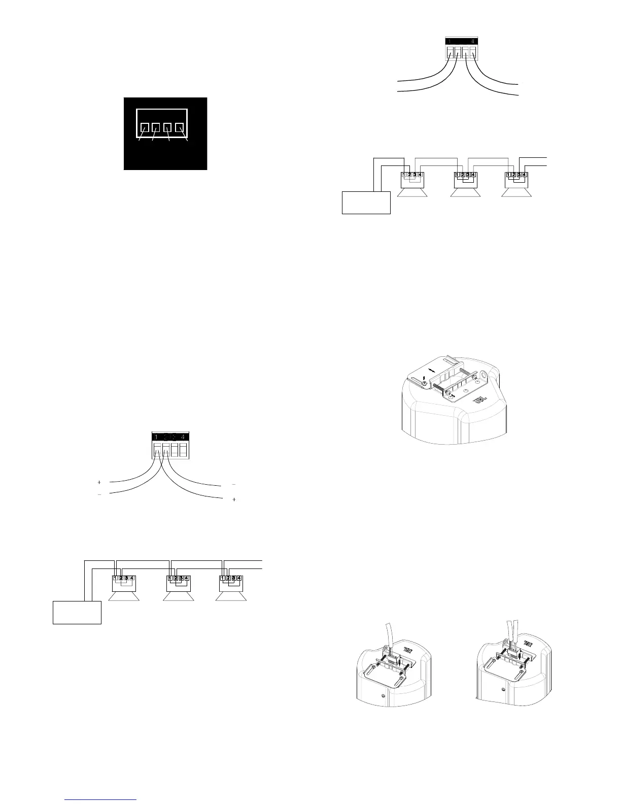
Guide to the Pins for Connection -- e removable locking
input connector contains 4 terminals, as marked on the con-
nector. e pin functions are listed on the label located on the
terminal cover plate.
1 2 3 4
+
IN
–
IN
+
Loop
Thru
–
Loop
Thru
Figure 6
Connecteor Pins
Pins 1 & 2 are the “+” and “-” inputs to the loudspeaker. Pins 1
& 2 are looped to pins 3 & 4, respectively (Pin 1 connects to Pin
3 and Pin 2 connects to Pin 4) inside the speaker. Pins 3 & 4 are
intended as loop-through connections to subsequent loud-
speakers. ere are two possible hookup schemes for connect-
ing subsequent speakers, determined by the desired result from
the circuit whenever this speaker’s connector gets disconnected
during troubleshooting:
Paralleling Input Terminals -- Connect the wire pair of the
subsequent speaker to pins 1 & 2 (in parallel with the input
wire pair). Whenever the connector is pulled out of the
speaker for troubleshooting, subsequent speakers will stay
connected. is can be useful during troubleshooting to
be able to disconnect a single loudspeaker at a time. In this
hookup scheme, no wires get connected to pins 3 & 4.
Figure 7:
Paralleling Input Terminals
-
+
Speaker 1 Speaker 2 Speaker 3
Power Amplifier
+
-
To
Subsequent
Speakers
Figure 8:
Parallel System Hookup Diagram
Using Loop-rough Terminals (Pins 3 & 4
) -- By connect-
ing the wire pair of the subsequent speaker to pins 3 & 4,
then all subsequent speakers will be disconnected when this
speaker’s connector is disconnected during troubleshooting,.
is can be useful as a way to isolate problems to a section
of the distributed line while leaving the wires attached to the
connector.
Figure 9:
Using Loop-Through Terminals
-
Speaker 1 Speaker 2 Speaker 3
Power Amplifier
+
-
To
Subsequent
Speakers
Figure 10:
Loop-Through System Hookup Diagram
Choose whichever hookup pattern accommodates your instal-
lation best.
Step 4 – Open the Strain Relief Fitting / Terminal
Cover
Figure 11:
Open the strain relief tting by loosening the two set screws in
the backcan, then loosen the two horizontal screws, and slide
open the sliding cover.
Loosen the screws holding the tting’s sliding piece of the in-
put-terminal cover and slide the cover open.
Step 5 – Plug connector into connector socket in
the speaker’s terminal cup.
Figure 12:
Plug Connector into Connector Socket. Shown with a single
cable (left) or with two cables for input and loop-through (right)
From Amplier
or Previous
Speaker
To Subsequent
Speaker(s)
+ - ‘
Power
Amplier
From Amplier
or Previous
Speaker
To Subsequent
Speaker(s)
To
Subsequent
Speaker(s)
+ - ‘
Power
Amplier
+
-
-
+
+
-
To
Subsequent
Speaker(s)