03
Connecting Your Subwoofer to Your
Amplifier
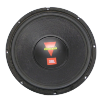
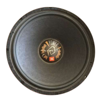
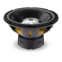
JBL GT Series subwoofers are available
in three different configurations: single
4-ohm voice coil, single 8-ohm voice coil
and dual 4-ohm voice coils. Depending
on the amplifier you are using, you may
use either single- or dual-voice-coil
subwoofers in singles or multiples to
maximize the power available from your
amplifier. To achieve the maximum
amplifier output possible, you should
design a speaker system that provides
the lowest impedance that your amplifier
is rated to drive safely. When designing
a subwoofer system, abide by the
following rules:
1. Don’t mix different subwoofer or enclo-
sure types in the same system (use all
single-coil 4-ohm woofers, all single-
coil 8-ohm woofers, or all dual-coil
woofers).
2. You may connect the coils of a dual-
voice-coil woofer in series, but NEVER
connect separate woofers in series.
Because the amplifier-damping factor
(the amplifier’s ability to control the
motion of the woofer) is expressed as
a ratio of terminal impedance (the sum
of speaker impedance, wire resistance
and the D.C. resistance of any
crossover coil connected to the
woofer) to amplifier-output imped-
ance, connecting woofers in series
reduces the damping factor of the
amplifier to a value less than 1. This
will result in poor transient response.
3. You must use both coils of a dual-
voice-coil woofer either in series or in
parallel.
4. Most amplifiers deliver exactly the
same amount of power bridged into
a 4-ohm load as they do running a
2-ohm stereo load.
To design a subwoofer system that
maximizes available amplifier power,
keep the following rules in mind:
1. The total system impedance of
woofers in parallel = 1/(1/w
1
+ 1/w
2
+
1/w
3
...) where w is the nominal imped-
ance of the woofer.
2. The total system impedance of voice
coils (or woofers) in series = w
1
+
w
2
+ w
3
...
The diagrams below and at right show
parallel and series speaker connections.
Figure 1. Parallel connection
Figure 2. Series connection