15c-1, 16c-1, 18z-1, 19c-1, 19c-1 PC 9
Cab & Switch Panel
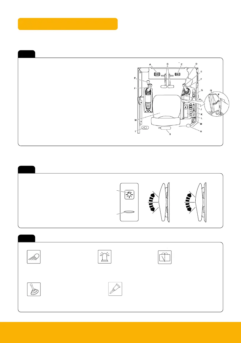
A Graphic symbol
B Light bar
C 3 way position switch
D 2 way position switch / momentary switch
Fig 7
About the Product
Console Switches
25 9831/2900-1 25
Console Switches
General
For: 16C-1, 18Z-1 ..................................................................................................................... Page 25
For: 19C-1 ................................................................................................................................ Page 26
(For: 16C-1, 18Z-1)
The installed switches and their positions can change according to the specification of the machine.
Each switch has a graphic symbol to show the function of the switch. Before you operate a switch, make sure
that you understand its function.
The rocker switches have two or three positions (as shown).
If the switch has a backlight, then the graphic symbol illuminates when the ignition switch or side lights are
in the on position.
The light bar illuminates to show that the switch function is active.
Figure 18.
1
3
2
A
B
A Graphic symbol B Light bar
About the Product
Console Switches
25 9831/2900-1 25
Console Switches
General
For: 16C-1, 18Z-1 ..................................................................................................................... Page 25
For: 19C-1 ................................................................................................................................ Page 26
(For: 16C-1, 18Z-1)
The installed switches and their positions can change according to the specification of the machine.
Each switch has a graphic symbol to show the function of the switch. Before you operate a switch, make sure
that you understand its function.
The rocker switches have two or three positions (as shown).
If the switch has a backlight, then the graphic symbol illuminates when the ignition switch or side lights are
in the on position.
The light bar illuminates to show that the switch function is active.
Figure 18.
1
3
2
A Graphic symbol B Light bar
Fig 6
A Auxiliary pedal
B Track Controls
C Swing left/ right
D Heater Controls
E Horn
F Excavator arm controls
G Dozer control lever
H Ignition switch
J Right console switches
K Hand throttle
L Instrument panel
M Radio (if installed)
N Operator seat
P Control isolation lever
Q Undercarriage track
extension lever
R Fire extinguisher (18z-1)
S Fire extinguisher (19c-1)
T Window washer bottle
Operator Station Layout – All Models
Switch Panel – 15C-1/16C-1/18Z-1/19C-1
C D
Work Lights
1 Off
2 On (Boom)
3 On (Boom & Cab)
Controls Isolation (2GO)
1 Off
2 Activate/de-activate
hydraulic controls
Bi-Directional and Hammer Mode Selector
1 Bi-directional mode – Double acting
2 Hammer mode – Single acting
Beacon
1 Off
2 On (Boom)
Window Wipers
1 Off
2 Intermittent/
continuos/washer
Fig 8
About the Product
Console Switches
27 9831/2900-1 27
H Aux 2 (low flow) selection
switch
No LED illumination
J Auto Idle on/off switch Not used.
K Beacon on/off switch LED illumination: Beacon on
L Q-Hitch sequence switch LED illumination: Q-Hitch solenoid on
Work Lights
(For: 16C-1, 18Z-1)
Two or three position rocker switch. The switch functions operate when the ignition
switch is in the on position.
Position : 1 = Off
Position : 2 = Boom and front cab work light on
Position : 3 = All work lights on
Beacon
(For: 16C-1, 18Z-1)
Two or three position rocker switch. The switch functions operate when the ignition
switch is in the on and off positions.
Position : 1 = Off
Position : 2 = Beacon on
Refer to: Beacon.
Controls Isolation
(For: 16C-1, 18Z-1)
Controls isolation switch. Two position momentary rocker switch. Press switch to
activate/de-activate the control.
Position : 1 = Rest position.
Position : 2 = Momentary position (activate/de-activate hydraulic controls).
Window Wipers
(For: 16C-1)
Three position rocker switch. The switch functions operate when the ignition switch is
in the on position. The wiper will self-park when switched off.
Position : 1 = Off
Position : 2 = On
Position : 3 = Washer on (if installed)
Bi-Directional and Hammer Mode Selector
(For: 16C-1, 18Z-1)
Two position rocker switch. The switch functions operate when the ignition switch is in
the on position and auxiliary has been selected.
Position 1: Bi-directional mode- Double acting attachment
Position 2: Hammer mode- Single acting attachment

 Loading...