01 - Machine
09 - Description
12 - Main Component Locations
01 - 21 9813/6750-1 01 - 21
12 - Main Component Locations
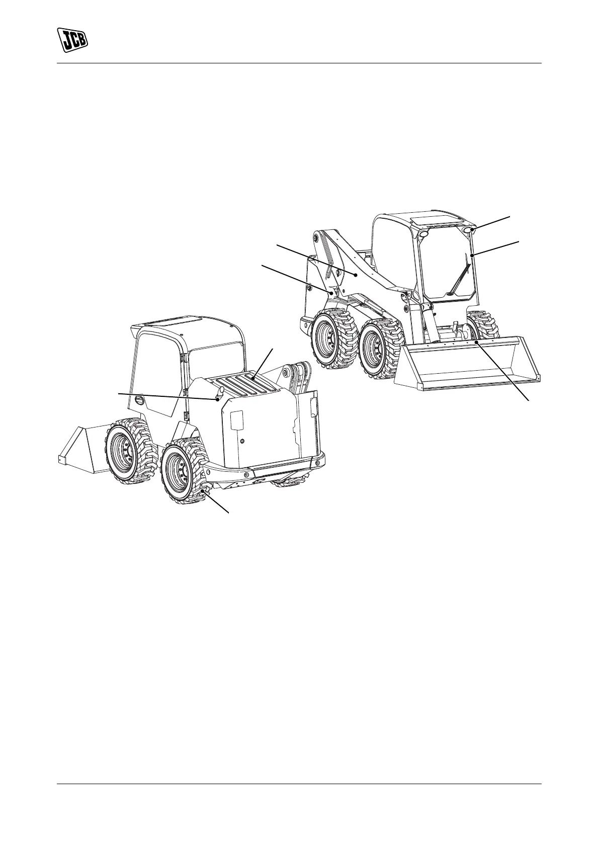
Introduction
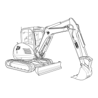
The illustration shows a typical machine model. Your
machine may look different from the one shown.
Figure 15.
1 ROPS/FOPS cab 2 Fuel tank filler point
3 Lift arm/boom 4 Front working lights
5 Quickhitch 6 Engine top cover
7 Wheels/tyres 8 Exhaust