10 Please see operator manual for full details.
Fig 6
Fig 7
D
A
N
Q
P
L
K J
H
G F
E
B
C
M
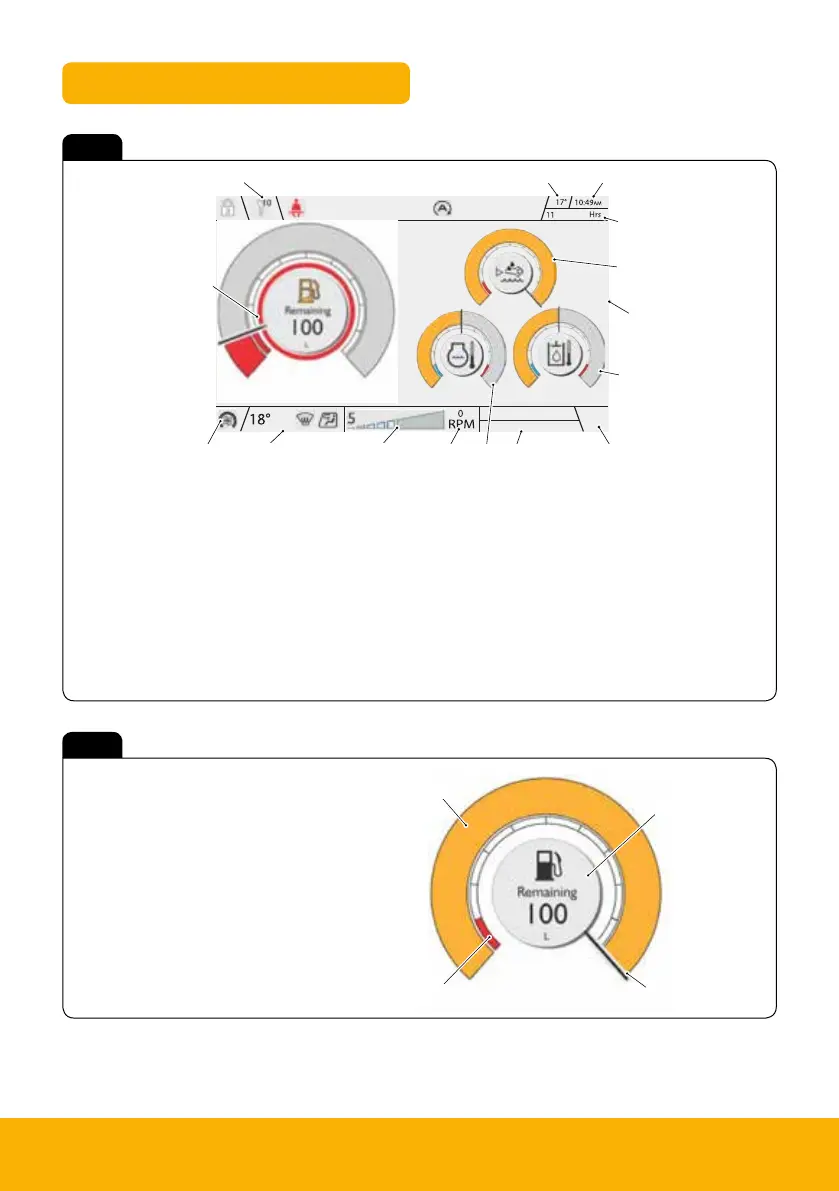
Instrument panel
C
D
A
B
A Upper ribbon icons
B Ambient temperature
C Clock
D Machine hours
E Camera screen (if camera mode selected)
F Volume or phone/media
G Source/detail information
H Engine RPM (Revolutions Per Minute)
A Warning band
B Main band
C Fuel information
D Needle
J Power band
K Lower ribbon HVAC
(Heating Ventilation Air Conditioning) icons
L HVAC/Fan speed
M Fuel level gauge
N Coolant temperature gauge
P DEF fluid level gauge
Q Hydraulic oil temperature gauge

 Loading...