06 - Body and Framework
24 - Slew Ring
00 - General
06 - 24 9813/5300-1 06 - 24
Remove and Install
(For: 6TST)
If the slew ring is to be removed it is important that
all the shims used in mounting the slew base onto
the slew ring and the slew ring onto the chassis
are recovered and that there original positions are
recorded. Failure to carry out this instruction will
result in the need to do the shimming procedure.
Remove
1. Make the machine safe. Refer to (PIL 01-03).
2. Remove the dumper body. Refer to (PIL 06-81).
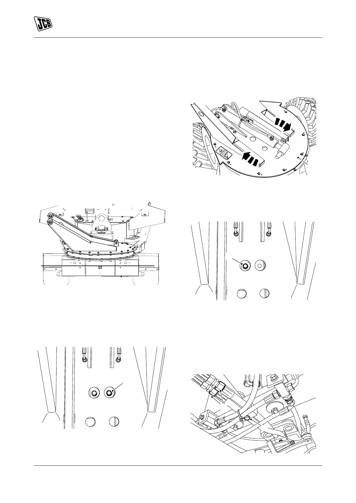
3. Turn the slew base to the specified angle.
Angle: 90°
Figure 15.
A Slew base
4. Discharge the hydraulic pressure. Refer to (PIL
30-00).
5. Remove the pin 1 from the slew ram 1.
6. Disconnect the slew ram 1.
Figure 16.
B Pin 1
7. Manually turn the slew base to the specified
angle whilst an assistant operates the hydraulic
control valve to prevent hydraulic lock-up.
Angle: 45°
Figure 17.
A Slew base
8. Remove the pin 2 from the slew ram 2.
9. Disconnect the slew ram 2.
Figure 18.
C Pin 2
10. Remove the hose brackets.
11. Disconnect the hydraulic hoses.
12. Put a label on the hoses to help installation.
13. Plug all the open ports and hoses to prevent
contamination.
Figure 19.
D Hose brackets