Do you have a question about the jcb Roto 512-83R and is the answer not in the manual?
The main screen showing operational information and status.
Visual alerts for machine status or potential issues.
Indicates engine speed in revolutions per minute (RPM).
Buttons to navigate up and down through menu options.
Displays the current fuel level in the tank.
Monitors the engine coolant temperature.
Activates or displays additional machine information.
Buttons for selecting and controlling individual outriggers.
Function to automatically deploy and level outriggers.
Function to automatically retract all outriggers.
Button to select the auto-leveling function for outriggers.
Button to lock the axle oscillation feature.
Buttons to control side sway adjustment of the outriggers.
Button to isolate or enable machine controls.
Button to activate or deactivate the auto idle function.
Levers for raising, lowering, extending, and retracting the boom.
Levers for tilting the carriage forward and backward.
Levers for rotating the superstructure clockwise and counterclockwise.
Restores full hydraulic service speed.
Activates the audible warning horn.
Button for setting a one-touch engine idle speed.
Function to override the machine's operating envelope limits.
Controls for auxiliary hydraulic functions.
Allows selection of different speed profiles.
Button to switch auxiliary service functions.
Enables or disables machine controls.
Initiates automatic deployment and leveling of all outriggers.
Switches for raising/lowering and extending/retracting outriggers.
Buttons to select specific outriggers for manual operation.
Button to initiate automatic retraction of outriggers.
Button to activate the automatic leveling feature.
Displays status of machine, chassis, and outrigger levels.
Information on current steer mode displayed on LCD screen.
Icons and notifications for changing between steer modes.
Access to the battery compartment.
Locations for hydraulic fluid, DEF, air filter, and fuel.
Switch to disconnect the battery power.
Procedure to disengage and engage carriage lock pins.
Steps to align carriage with attachment hook plates.
Engaging support bar and ensuring hook plates are engaged.
Ensuring park brake is on and transmission is in neutral.
Procedure for stopping the engine and removing the key.
Securing the manual locking lever and optional carriage lock pin.
Connecting hydraulic hoses for slew-type platforms.
Final step to connect the electrical connector.
Locating engine oil dipstick, coolant, radiator, water separator, and fuel filter.
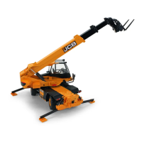
The JCB Roto 512-83R is a versatile telehandler designed for a wide range of material handling and lifting tasks. This Quick Reference Guide provides essential information for its operation, technical specifications, and maintenance, though it emphasizes that it does not replace the comprehensive Operator's Manual. Users are strongly advised to consult the full manual for all disclaimers, safety instructions, and detailed operational procedures.
The JCB Roto 512-83R is primarily used for lifting, carrying, and placing materials, often in construction, agriculture, and industrial settings. Its rotating superstructure allows for precise load placement without needing to reposition the entire machine, enhancing efficiency and safety on job sites. The machine features a robust boom system, outriggers for stability, and various steer modes for maneuverability.
The static dimensions of the JCB Roto 512-83R are crucial for transport, site planning, and operational clearances:
These dimensions highlight the machine's substantial footprint and reach, which are critical for safe operation and transport.
The JCB Roto 512-83R is equipped with a sophisticated control system and various operational features designed for precision, safety, and ease of use.
The operator's cab is designed for ergonomic control and clear visibility. Key components include:
The instrument panel provides critical feedback to the operator:
The machine features dedicated buttons for outrigger control:
The chassis levelling system allows the operator to maintain a level machine on uneven terrain, crucial for safe lifting. The display shows:
The JCB Roto 512-83R offers multiple steer modes for enhanced maneuverability:
The joysticks provide intuitive control over the boom and carriage:
Pressing and holding the auto deploy button on the keypad for 2 seconds automatically extends all outriggers and then lowers them until deployed, leveling the machine to +/- 0.5°. This feature significantly simplifies setup on uneven ground.
The process for connecting attachments is detailed to ensure safety and proper engagement:
For transport, the machine must be secured properly:
The JCB Roto 512-83R includes easily accessible compartments for routine maintenance checks.
Regular checks of these components are essential for the longevity and reliable operation of the JCB Roto 512-83R. Always refer to the Operator's Manual for detailed maintenance schedules and procedures.
| Brand | jcb |
|---|---|
| Model | Roto 512-83R |
| Category | Excavators |
| Language | English |