
T
Timothy BlackSep 9, 2025
Why does the JCM GLOBAL UBA Pro RT Industrial Equipment transport LED flash 1 time?
- MMrs. Robin GoldenSep 9, 2025
A possible cause is Recycler Drum 1 and/or Drum 2 timeout in the RQ Transport.
Why does the JCM GLOBAL UBA Pro RT Industrial Equipment transport LED flash 1 time?
A possible cause is Recycler Drum 1 and/or Drum 2 timeout in the RQ Transport.
What does it mean when the JCM GLOBAL Industrial Equipment status LED flashes 4 times?
A possible cause is that Recycler Drum 1 and/or Drum 2 is full in the RT Transport.
What does it mean when the JCM GLOBAL UBA Pro RT Industrial Equipment transport LED flashes 4 times?
A possible cause is that Recycler Drum 1 and/or Drum 2 is full in the RQ Transport.
What does it mean when the JCM GLOBAL UBA Pro RT Industrial Equipment status LED flashes 5 times?
A possible cause is a Transport Motor Speed error in the RT Transport.
What does it mean when the JCM GLOBAL UBA Pro RT Industrial Equipment transport LED flashes 5 times?
A possible cause is a Transport Motor Speed error in the RQ Transport.
What does it mean when the JCM GLOBAL UBA Pro RT Industrial Equipment status LED flashes 6 times?
A possible cause is a Recycler Drum 1 and/or Drum 2 speed adjustment error in the RT Transport.
What does it mean when the JCM GLOBAL UBA Pro RT Industrial Equipment status LED flashes 9 times?
A possible cause is a Flapper Lever error in the RT Transport.
What does it mean when the JCM GLOBAL UBA Pro RT transport LED flashes 9 times?
A possible cause is a Flapper Lever error in the RQ Transport.
Why does the JCM GLOBAL UBA Pro RT status LED flash 1 time?
A possible cause is a ROM error (Boot I/F).
What does it mean when the JCM GLOBAL UBA Pro RT Industrial Equipment status LED flashes 10 times?
A possible cause is a Flapper Motor lock-up in the RT Transport.
Overview of RT and RQ units, compatible with UBA Pro Series Banknote Acceptor.
Description of the RT/RQ product model number specifications.
Description of the RT/RQ type number specifications.
Description of the RT/RQ software number specifications.
User and installation cautions for safe operation and unit integrity.
Cautions for unit installation regarding environment and vibration.
Methods for mounting, dismounting, and transporting the unit.
Cautions to be observed during unit operation for safety and performance.
Requirements for routine cleaning and maintenance to ensure optimal performance.
Requirements for the proper disposal of batteries and units.
Types of banknotes that may cause jams or damage and should be avoided.
Highlights key features of the RT/RQ Unit, including recycler capacity and processing speed.
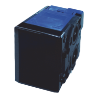
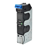
Illustrates and names the RT/RQ components and their locations.
Technical, environmental, electrical, and structural specifications for the RT/RQ Unit.
Illustrates unit dimensions and required installation/maintenance space.
Contact details for JCM offices worldwide for technical support.
Steps for installing the RT/RQ Unit into its designated location.
Procedure for connecting the frame housing to the frame ground for safety.
Procedure for performing side mounting configuration for standard and SU types.
Procedure for bottom mounting configuration for standard installation type.
Steps to install the bezel onto the UBA Pro Unit.
Steps to connect and secure the power and interface harnesses.
Information on installing security locks onto the cash box.
Instructions for unlocking the cash box using installed locks.
Configuration settings for DIP switches on the unit.
Indicates LED color patterns for operating and error conditions.
Pin assignments for various unit connectors.
Procedures for routine cleaning and maintenance of the unit.
Steps to clear jammed banknotes from various unit sections.
Procedure for cleaning sensors, rollers, and belts.
Circuit schematics for standard interfaces.
Flowcharts detailing unit operational processes.
Contact information for JCM American support.
Contact information for JCM Europe GmbH support.
Contact information for JCM Europe (UK Office) support.
Contact information for JCM Gold (HK) Ltd. and HQ.
Lists the necessary tools for performing disassembly and reassembly.
Steps to remove the UBA Pro Unit, Recycler, and Cash Box from the frame.
Steps to remove the transport unit in the RT Transport.
Steps to remove the transport unit in the RQ Transport.
Steps to remove the RT Frame Unit.
Steps to remove the RQ Frame Unit.
Detailed steps for disassembling the RT Frame Unit.
Steps to remove the Flap Board from the RT Frame Unit.
Steps to remove the Flap Home Board from the RT Frame Unit.
Steps to remove the transport board.
Steps to remove the cylinder lock.
Steps to remove the key plate.
Steps to remove the LED board.
Steps to remove the front transport unit from the RT Frame Unit.
Steps to remove the rear transport unit from the RT Frame Unit.
Steps to remove the flap motor harness assembly.
Steps to remove the TR worm gear (twin).
Steps to remove the TR motor harness assembly.
Steps to remove the status LED/collect button.
Steps to remove timing belts from the RT rear transport unit.
Steps to remove back transport gear 1.
Detailed steps for disassembling the RQ Frame Unit.
Steps to remove the Flap Board from the RQ Frame Unit.
Steps to remove the Flap Home Board from the RQ Frame Unit.
Steps to remove the front transport unit from the RQ Frame Unit.
Steps to remove the rear transport unit from the RQ Frame Unit.
Steps to remove the flap motor harness assembly from the RQ Frame Unit.
Steps to remove the TR worm wheel (twin).
Steps to remove the quad TR motor harness assembly.
Steps to remove timing belts.
Common disassembly steps for RT/RQ Frame Units.
Steps to remove sponge roller assembly from the rear transport unit.
Steps to remove sponge roller assembly from the front transport unit.
Steps to remove timing belts from the transport unit.
Detailed steps for disassembling the recycler.
Steps to remove the tape board.
Steps to separate the drum unit.
Steps to remove sponge roller assembly from drum 1 side.
Steps to remove rubber pulleys and drive rollers from drum 1 side.
Steps to remove the solenoid.
Steps to remove sponge roller assembly from drum 2 side.
Steps to remove rubber pulley and drive roller from drum 2 side.
Steps to remove motor harness assembly.
Steps to remove clear film and DET film.
Wiring diagram illustrating the connections between RT/RQ units and host.
Lists tools and equipment needed for calibration and performance testing.
Steps to install the JCM Tool Suite application and USB Drivers.
Explains Normal Mode, Test Mode, and Service Mode features of the JCM Tool Suite.
Procedures for downloading software programs onto the unit.
Instructions for performing unit calibration.
Instructions for conducting performance tests using a PC interface.
Lists performance tests that can be conducted without a PC.
Detailed list of performance test items for RT/RQ units.
Steps to launch the performance test program.
Procedure to test the status LED performance.
Procedure to test the RT/RQ Unit DIP Switch performance.
Instructions for conducting performance tests on RT Transport without PC.
Instructions for conducting performance tests on RQ Transport without PC.
Exploded view illustration of the complete RT Entire Unit.
List of all parts for the RT Entire Unit with EDP numbers and descriptions.
Exploded view illustration of the complete RQ Entire Unit.
List of all parts for the RQ Entire Unit with EDP numbers and descriptions.
Exploded view of the RT (Twin) Frame Unit, part 1.
Parts list for the RT (Twin) Frame Unit, part 1.
Exploded view of the RT (Twin) Frame Unit, part 2.
Parts list for the RT (Twin) Frame Unit, part 2.
Exploded view of the RT (Twin) Frame Unit, part 3.
Parts list for the RT (Twin) Frame Unit, part 3.
Exploded view of the RT (Twin) Frame Unit, part 4.
Parts list for the RT (Twin) Frame Unit, part 4.
Exploded view of the RT (Twin) Frame Unit, part 5.
Parts list for the RT (Twin) Frame Unit, part 5.
Exploded view of the RT (Twin) Frame Unit, part 6.
Parts list for the RT (Twin) Frame Unit, part 6.
Exploded view of the RT (Twin) Frame Unit, part 7.
Parts list for the RT (Twin) Frame Unit, part 7.
Exploded view of the RT (Twin) Frame Unit, part 8.
Parts list for the RT (Twin) Frame Unit, part 8.
Exploded view of the RQ (Quad) Frame Unit, part 1.
Parts list for the RQ (Quad) Frame Unit, part 1.
Exploded view of the RQ (Quad) Frame Unit, part 2.
Parts list for the RQ (Quad) Frame Unit, part 2.
Exploded view of the RQ (Quad) Frame Unit, part 3.
Parts list for the RQ (Quad) Frame Unit, part 3.
Exploded view of the RQ (Quad) Frame Unit, part 4.
Parts list for the RQ (Quad) Frame Unit, part 4.
Exploded view of the RQ (Quad) Frame Unit, part 5.
Parts list for the RQ (Quad) Frame Unit, part 5.
Exploded view of the front transport unit, part 1.
Parts list for the front transport unit, part 1.
Exploded view of the front transport unit, part 2.
Parts list for the front transport unit, part 2.
Exploded view of the transport unit, part 1.
Parts list for the transport unit, part 1.
Exploded view of the transport unit, part 2.
Parts list for the transport unit, part 2.
Exploded view of the transport unit, part 3.
Parts list for the transport unit, part 3.
Exploded view of the rear transport unit for RT frame, part 1.
Parts list for the rear transport unit for RT frame, part 1.
Exploded view of the rear transport unit for RT frame, part 2.
Parts list for the rear transport unit for RT frame, part 2.
Exploded view of the rear transport unit for RT frame, part 3.
Parts list for the rear transport unit for RT frame, part 3.
Exploded view of the rear transport unit for RQ frame, part 1.
Parts list for the rear transport unit for RQ frame, part 1.
Exploded view of the rear transport unit for RQ frame, part 2.
Parts list for the rear transport unit for RQ frame, part 2.
Exploded view of the rear transport unit for RQ frame, part 3.
Parts list for the rear transport unit for RQ frame, part 3.
Exploded view of the recycler, part 1.
Parts list for the recycler, part 1.
Exploded view of the recycler, part 2.
Parts list for the recycler, part 2.
Exploded view of the recycler, part 3.
Parts list for the recycler, part 3.
Exploded view of the recycler, part 4.
Parts list for the recycler, part 4.
Exploded view of the recycler, part 5.
Parts list for the recycler, part 5.
Exploded view of the recycler, part 6.
Parts list for the recycler, part 6.
Exploded view of the recycler, part 7.
Parts list for the recycler, part 7.
Exploded view of the recycler, part 8.
Parts list for the recycler, part 8.
Exploded view of the recycler, part 9.
Parts list for the recycler, part 9.
Exploded view of the recycler, part 10.
Parts list for the recycler, part 10.
Exploded view of the recycler, part 11.
Parts list for the recycler, part 11.
Exploded view of the box connect module.
Parts list for the box connect module.
Exploded view of the SH2 Box (400 Notes) Frame.
Parts list for the SH2 Box (400 Notes) Frame.
Exploded view of the Large Box (800 Notes) Frame.
Parts list for the Large Box (800 Notes) Frame.
Procedures for clearing banknote jams from the unit.
Methods and equipment required for cleaning the unit's components.
Information regarding communication criteria and contact details.
Addresses and telephone numbers for JCM offices worldwide.
Illustrated drawing of the entire unit's clearance requirements.
Instructions for performing unit disassembly and reassembly.
Instructions for performing the driver installation.
Illustrations of exploded views for unit components.
Operational flowcharts detailing unit processes.
Required steps for installing the unit.
Procedure for navigating within the manual.
Preparation steps for PC-based calibration.
Key features of the UBA-5x0-SH2/SS-RT/RQ and UBA Pro RT/RQ Series.
Acronym definition for UBA Pro RT/RQ Series Banknote Recycler.
Pictographs indicating safety symbols and their meanings.
Specifications of software descriptions for the unit.
Italic text highlights and finger points for special notes.
Sequential numbering of steps in procedures.
Types of symbols used for precautions.
Instructions for troubleshooting common issues.
Specifications of product type descriptions.
Definition of UBA Pro Universal Banknote Acceptor acronym.
Introduction to troubleshooting the UBA Pro RT/RQ Series Banknote Recycler.
Overview of fault diagnosis and repair procedures for the product.
Indicates various error codes via LEDs for RT/RQ Unit errors.
Lists error code indications for Status, Recycler, and Transport LEDs.
Guidelines for handling reference paper used in calibration.
List of additional maintenance equipment parts, including reference paper.
Device that validates and accepts banknotes, communicating results to the Host Machine.
Prevents unauthorized retrieval of banknotes from the cash box.
Plastic assembly with an access opening for banknote insertion and retrieval.
Process to ensure circuits are aligned and operating at optimum levels.
Assembly designed to center banknotes entering the acceptor at a skewed angle.
Numerical value verifying data file integrity during transmission or encryption.
Method to increase safety by isolating transmitted data signals.
Internationally recognized safety and attention symbols used in manuals.
Unit programmed to accept and recycle banknotes, working with payment systems.
Notations alerting readers to specific information affecting unit operation.
| Model | UBA Pro RT Series |
|---|---|
| Category | Industrial Equipment |
| Manufacturer | JCM GLOBAL |
| Operating Temperature | 0°C to 50°C |
| Stacker Capacity | 500 notes |
| Power Supply | 12V DC |
| Certifications | CE, UL |