Do you have a question about the JCM WBA Series and is the answer not in the manual?
Provides an overview of the WBA Series and manual navigation.
Details WBA model number specifications including head type, CPU, box type, etc.
Lists safety warnings and user cautions for operation and handling.
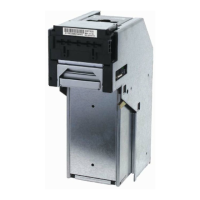
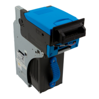
Identifies and illustrates major component parts of the WBA.
Provides detailed technical, environmental, electrical, and structural specifications.
Illustrates the typical WBA system configuration and connections.
Lists key features like interchangeable bill guides and DIP switch programmability.
Shows standard unit dimensions in millimeters.
Lists country codes used for currency identification.
Provides step-by-step instructions for installing the WBA unit.
Illustrates WBA input/output circuit diagrams for different models.
Details pin assignments for various WBA connectors (CN1, CN2, CN3, Rear Panel).
Shows typical cabling requirements between the Host machine and WBA.
Lists default DIP switch configurations and their functions.
Illustrates differences in head sensor lens configurations between WBA-1X and WBA-2X.
Explains the steps to retrieve deposited bills from the cash box.
Provides instructions for clearing bill jams at the entrance and transport path.
Details important cleaning procedures and warnings for maintaining the unit.
Introduces the authorized Waffletechnology cleaning card.
Depicts the bill acceptance flow process for the ID-003 interface.
Lists the necessary tools for disassembly and reassembly procedures.
Provides initial steps for disassembling the WBA unit's primary parts.
Details steps for disassembling the WBA acceptor unit.
Details steps for removing the WBA acceptor's upper sensor circuit board.
Details steps for removing the WBA acceptor's lower sensor circuit board.
Explains how to remove the WBA acceptor's belt tension assembly.
Provides steps for removing the transport unit's CPU circuit board.
Details removing the transport CPU board assembly for specific models.
Explains how to remove the stacker encoder sensor board.
Provides steps for removing the WBA transport's stack motor.
Details removing the transport unit's encoder sensor board.
Explains how to remove the WBA transport's drive motor.
Details removing the WBA entrance lever sensor board.
Provides steps for removing the WBA solenoid lever assembly.
Details removing the WBA solenoid lever sensor board.
Explains how to disassemble the transport's feed-out sensor assembly.
Details steps to begin removing the transport's upper timing belts.
Provides steps for removing the transport's home position sensor board.
Continues the procedure for removing the transport's upper timing belts.
Details steps for removing the transport's lower timing belts.
Details removing the WBA cash box pusher mechanism cover.
Provides steps for removing the WBA cash box pusher mechanism.
Explains how to remove the pusher mechanism timing belts.
Details the complete disassembly procedure for the WBA cash box.
Shows a diagram of the WBA's primary components.
Provides the system wiring diagram for the WBA-14-SS3B model.
Provides the system wiring diagram for the WBA-15-SS3B model.
Provides the system wiring diagram for the WBA-24-SS3B model.
Provides the system wiring diagram for the WBA-25-SS3B model.
Lists the tools required for workbench software downloads.
Describes steps for decompressing and storing downloaded programs.
Details the steps for performing calibration using the adjustment program.
Illustrates the screen for white paper calibration.
Illustrates the screen for black paper calibration.
Shows the screen for removing calibration paper.
Illustrates the screen for magnetic test calibration.
Prompts to save adjustment data to memory.
Confirms that adjustment data writing is complete.
Indicates that all calibration procedures are complete.
Explains error messages that appear during calibration.
Lists sensor signal names and their comparisons for WBA models.
Provides an exploded view of the entire WBA unit.
Lists all parts for the entire WBA unit.
Shows an exploded view of the WBA 12/13 acceptor head.
Shows an exploded view of the WBA 22/23/24/25 acceptor head.
Lists collective parts for WBA 12/13 and 22/23/24/25 acceptor heads.
Lists parts for the WBA transport unit.
Shows continued exploded views of the WBA transport unit.
Shows an exploded view of the WBA frame unit.
Lists parts for the WBA frame unit.
Shows an exploded view of the WBA cash box unit.
Shows continued exploded views of the WBA cash box unit.
Lists collective parts for the WBA cash box.
Provides installation steps and procedures.
Lists general faults and their corrective actions.
Details electrical, environmental, structural, and technical specifications.
Introduces troubleshooting information and basic checks.
Explains the process of fault diagnosis using fault table listings.
Lists general fault conditions and their possible causes and corrective actions.
Lists faults related to calibration adjustments and their causes.
Lists communication faults and their corrective actions.
Describes diagnostic tests to identify failure conditions using DIP Switches.
Explains how to enter and perform the auto calibration mode.
Details how to enter the diagnostic test mode for WBA units.
Provides DIP switch settings for performing various functional tests.
Explains how to enter and perform the head sensor test.
Provides DIP switch settings for WBA-1X/2X head sensor tests.
Illustrates the locations of head sensors on WBA units.
Details how to enter and perform the transport sensor test.
Provides DIP switch settings for WBA-1X/2X transport sensor tests.
Illustrates sensor locations in the WBA transport unit.
Shows locations of sensors, circuit boards, and motors in the WBA.
Explains how to run bill acceptance tests.
Provides steps to initiate a forced download of software.
Details the steps for initiating a DT-004 software download.
Explains the steps for initiating a PC software download.
Lists abnormal operation codes for WBA-1X/2X.
Lists abnormal operation codes specific to Test Mode 4.
Lists return error codes for WBA-1X/2X.
Term for functions sent to/from the Bill Acceptor via software.
Codes identifying a country for currency type.
Dual Inline Package Switch for configuration.
LED and photo sensor combination for isolating electrical signals.
Safety and attention symbols used in the manual.
Device used to stack received bills.
Acronym for World Bill Acceptor.
| Brand | JCM |
|---|---|
| Model | WBA Series |
| Category | Cash Register |
| Language | English |