35
The screen should be made of light colored material and should have a black center line for use in centering the screen with the
vehicle. The screen should also have two vertical black lines, one on each side of the center line at a distance equal to the lamp
centers.
Place the vehicle on the floor with the tires inflated to the recommended pressure for highway use. Set the vehicle 25 feet (7.62
in.) from the front of the screen or wall, so that the center line of the vehicle is in line with the center line on the screen. To
position the vehicle, stand at the rear and sight through the windshield down across the cowl and hood.
Measure from the floor to the center of the headlamp and mark a horizontal line on the screen 4½ inches (114.30 mm.) less.
Turn on the headlamp upper beam, cover one lamp and check the location of the beam on the screen. The center of the “hot spot”
should be centered on the intersection of the vertical and horizontal lines.
If the aim is incorrect, remove the headlamp door screw and remove the door, then adjust the two screws in the mounting ring to
move the headlamp unit until the beam is correctly aimed, then tighten.
Cover the headlamp aimed and adjust the other in the same manner.
CLUTCH.
The clutch is of the single, dry plate type consisting of a pressure plate assembly, having three pressure springs, three release
levers; and a spring cushioned, faced driving plate mounted on a hardened steel, splined hub. Clutch release is accomplished by
moving the release bearing toward the flywheel. The three springs located in the clutch bracket provide the driving pressure, thus,
when the foot pressure is removed from the pedal, the springs force the pressure plate forward against the driven plate, gradually
and smoothly applying power to the wheels.
As the clutch facings wear, the clearance between the release levers and the release bearing is decreased. The effect on the clutch
pedal is to decrease the free travel, which is the distance the pedal moves away from the toe board before the release bearing
comes into contact with the release levers. Adjusting the length of the clutch control cable to increase the free travel of the clutch
pedal, restores the proper clearance between the release levers and the release bearing. See Fig. 19. The release bearing and
clutch pedal must be in their proper positions. No adjustment of the clutch proper is required to compensate for wear of the
facings, but a clearance of approximately 1/8” (3.17 mm.) should be maintained between the release levers Fig. 21 No. 14 and the
release bearing No. 7. To obtain this clearance, adjust the length of the clutch control cable No. 18, so that the pedal has 1-1/4”
(31.75 mm.) free movement from the fully engaged position before any resistance can be felt.
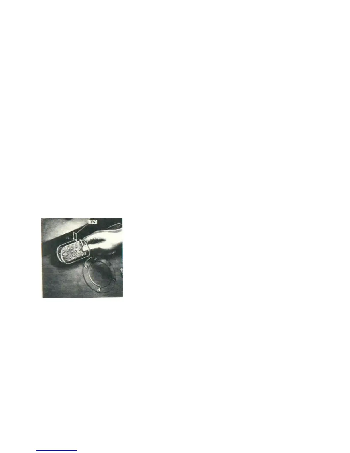
FIG. 19CLUTCH PEDAL ADJUSTMENT
PDF created with pdfFactory trial version www.pdffactory.com
 Loading...