49
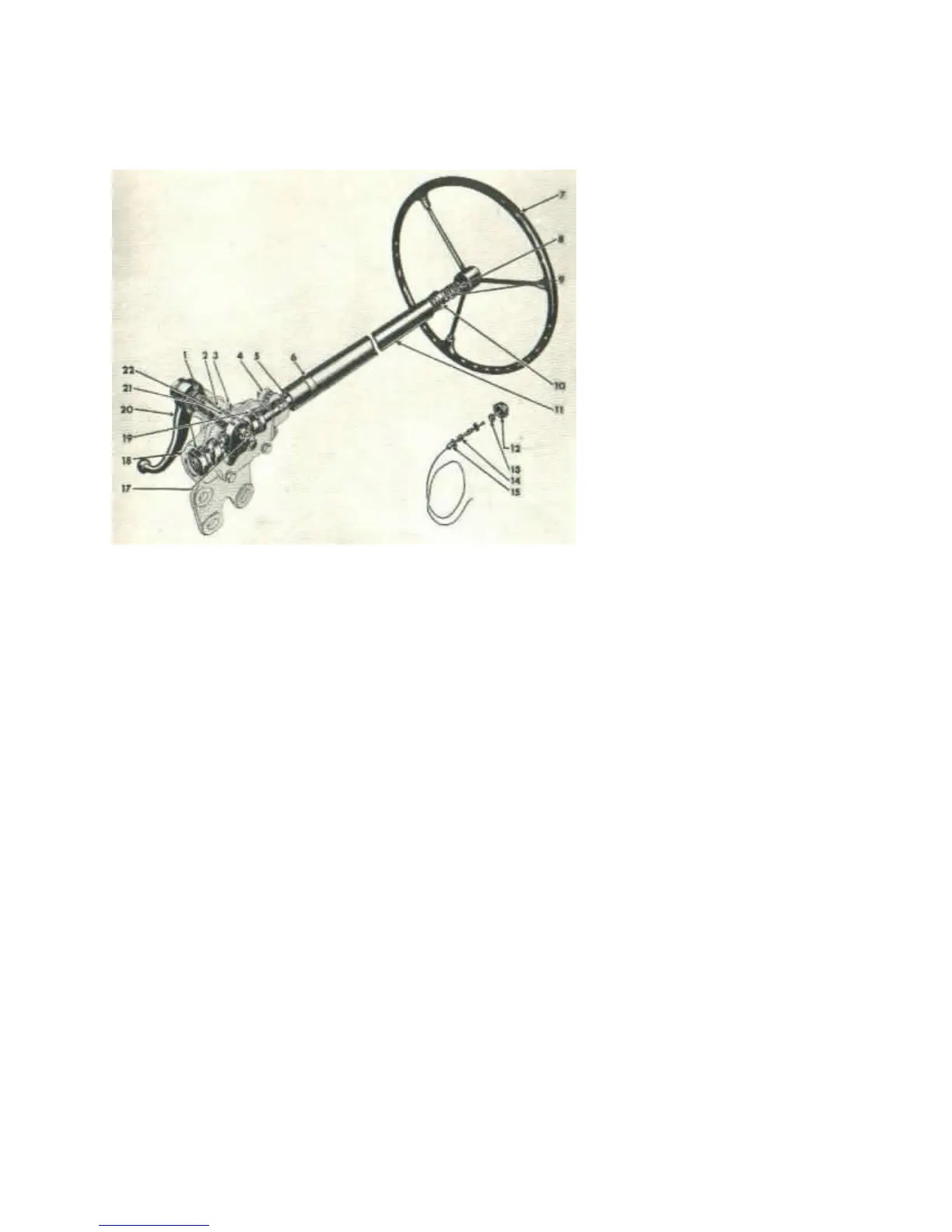
FIG. 31--STEERING GEAR
1—Housing Oil Seal12—Steering Wheel & Horn Button Nut
2—Lever Shaft Assembly13—Horn Button
3—Housing Oil Filler Plug14—Horn Button Spring
4—Steering Column Clamp Assembly15—Horn Button Spring Cup
5—Cam & Wheel Tube Assembly17—Side Adjusting Screw
6—Steering Column Oil Hole Cover18—Housing Assembly
7—Steering Wheel19—Cam Bearing Balls
8—Steering Column Bearing Spring20—Steering Gear Arm
9—Steering Column Bearing Spring Seat21—Housing Bushing—Inner
10—Steering Column Bearing Assembly22—Housing Bushing—Outer
11—Steering Column & Bearing Assembly
FRONT WHEEL BEARINGS.
The front wheels are mounted on two opposed tapered roller bearings. These bearings are adjustable for wear and
their satisfactory operation and long life depends upon periodic attention and correct lubrication.
Loose front wheel bearings may cause excessive wear and will affect front wheel alignment. If the bearing
adjustment is too tight, the rollers may break or become overheated.
To check the adjustment, first raise the front of the vehicle so that the tires clear the floor. Check the brakes to be
sure they are free and fully released. With the hands, check sidewise shake of the wheel. If the bearings are correctly
adjusted, shake of the wheel will be just perceptible and the wheel will turn freely with no drag.
Should the test indicate that adjustment is necessary, remove the hub cap, axle shaft nut and washer, driving flange
and shims. See Fig. 25. Wheel bearing adjustment will then be accessible. Bend the lip of the nut locking washer so
that the adjusting nut lock nut and washer can be
PDF created with pdfFactory trial version www.pdffactory.com
 Loading...