63
Some power take-off assemblies are supplied with a 1 to 1 gear ratio to provide one standard output shaft speed and are so
identified. Other assemblies are equipped with a gear ratio of 5 to 6 (20 teeth to 24 teeth), the gears of which may be
interchanged to vary the output shaft speed in relation to vehicle ground speed.
When towing power-driven farm machines under average conditions, best operation will be secured by using either No. 5
or 6 governor control position with both the transmission and transfer case gears in the low range position. Reference to
the tables on Pages 67 and 68 will give vehicle ground speed and shaft speed in these operating positions for power
takeoff assemblies equipped with each of the shaft gear ratios.
The shaft speed of the power take-off assemblies equipped with the 1 to 1 ratio cannot be changed. The shaft speed, in
relation to vehicle ground speed, can be changed in assemblies equipped with the 5 to 6 ratio, however, by interchanging
the gears.
Under heavy crop conditions, it may be found that the machine being operated cannot handle the volume of crop which is
cut at the vehicle ground speed necessary to maintain power take-off shaft speed. To handle the crop, it is necessary to
reduce vehicle ground speed without changing the power take-off shaft speed. This is accomplished by interchanging
Gears No. 33 and No. 15, as shown in Fig. 36. The original factory installation is made to provide a ratio of 5 to 6—the
20 tooth gear being assembled on the input shaft and the 24 tooth gear on the output shaft, as shown in Fig. 36,
To interchange the gears, first remove the power take-off assembly from the vehicle and drain the lubricant from the
housing. Remove the bearing retaining plate No. 11, Fig. 36. Bend back the lips of the nut locking washer and remove the
bearing retaining nut. The cover may then be removed with the bearing assembly. Use care not to lose the shims which
are placed between the gear hub and the bearing cone. The gear may be slipped from the shaft through the cover opening.
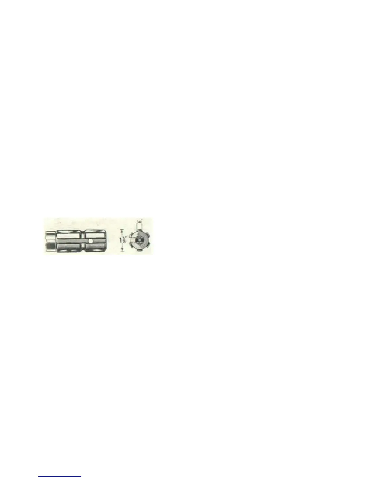
FIG. 38—POWER TAKE-OFF SHAFT
The other gear may be removed in the same manner after removing cover plate. Interchange the gears and reassemble in
the reverse order with the long side of the gear hub toward the cover opening. Use care that the shims are replaced in the
same position relative to the bearings from which they were removed. Do not overlook refilling the housing with
lubricant.
The speed of the output shaft in relation to vehicle ground speed is important. To aid in the selection of engine speeds and
gear ratio positions, refer to the charts on Pages 67 and 68 which show both the shaft and vehicle speeds, with power
take-off assemblies having each ratio, through the range of governor controlled engine speeds and in all transmission and
transfer case gear positions.
PDF created with pdfFactory trial version www.pdffactory.com
 Loading...