6
-
8
Chapter
6
Emissions and engine control systems
airstream flowing through the venturi. These vapors pass through the
intake manifold into the combustion chambers, where they are con
-
Checking
sumed during combustion.
5
The fuel filler cap incorporates a two
-
way relief valve that is closed
6
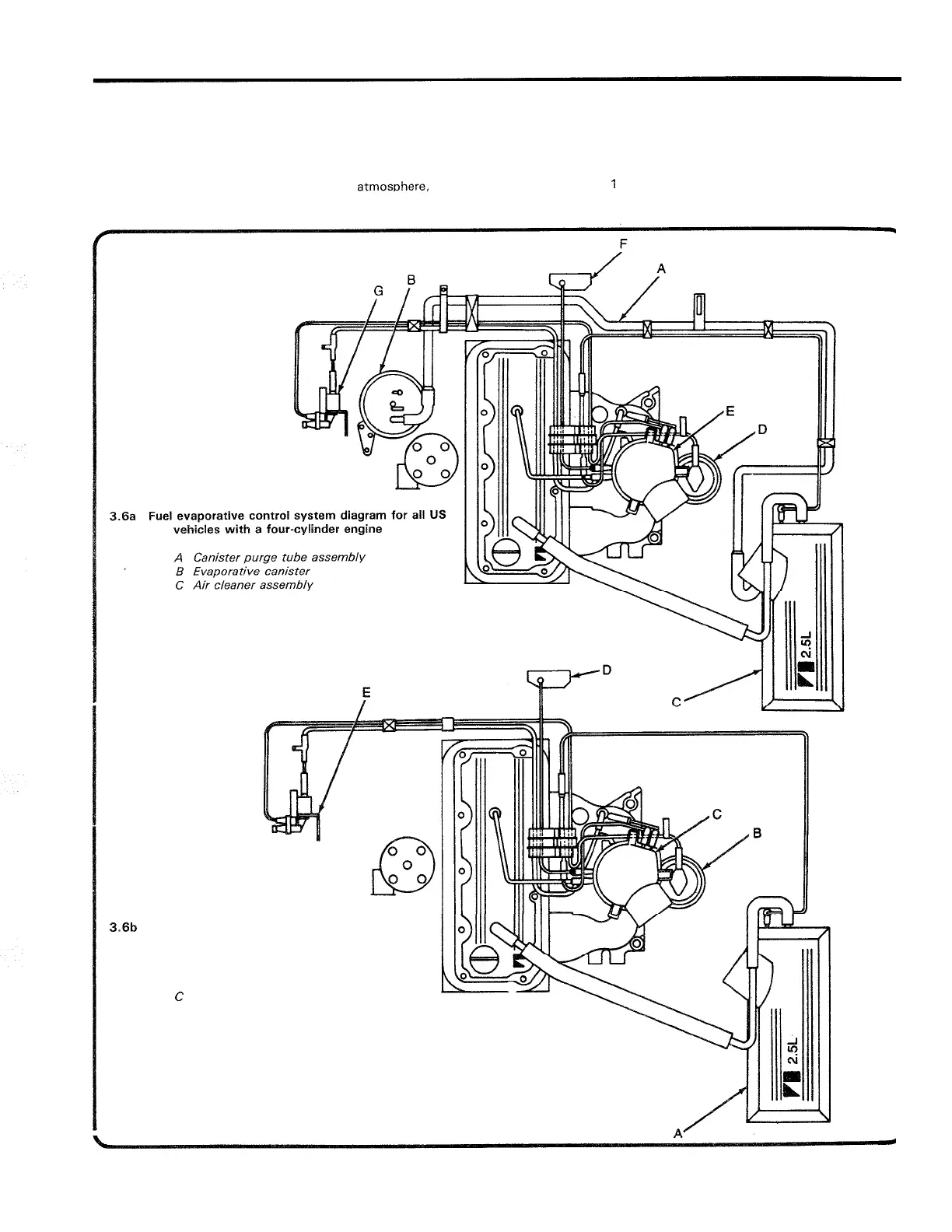
Periodically, inspect the evaporative system vacuum hoses to be
during normal operating conditions. The relief valve is calibrated to open
sure they are attached and in good condition. Refer to the accom
-
when the fuel tank has
a
pressure of
1.5
psi, or a vacuum of
1.8
in
-
Hg.
panying vacuum hose routing diagrams
(see illustrations).
Once the oressure or vacuum is relieved to the atmos~here, the valve
7
See Chapter
1
for information regarding routine maintenance of
returns to its normally closed position.
the canister.
D
EGR valve
E
Throttle body assembly
F
MAP sensor
G
EGR solenoid
3.6b
Fuel evaporative control system diagram for
Canadian vehicles with a four
-
cylinder engine
A Air cleaner assembly
B
EGR valve
C
Throttle body assembly
D
MAP sensor
E
EGR solenoid
 Loading...