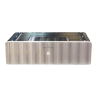
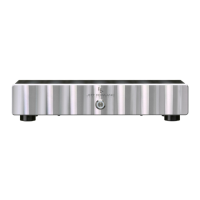
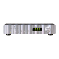
Front & Rear Panel Function Controls
Before attempting any system interconnection, please familiarize yourself
with the front and rear panel controls of the Model 8T/Ti Amplifier. The
descriptions below refer to the numbers and letters associated with the
features in the diagram above.
Front Panel
A
FRONT PANEL STANDBY/POWER button: Press to operate
Amplifier. Press again to place Amplifier in standby mode. This button
will illuminate when the Amplifier is operational. When the button is
not illuminated, all Amplifier inputs are muted and internal circuitry is
reverted to power-saving (standby) mode. Note: All ON/OFF power
switching should be initiated ONLY with this button. Anomalous
operating conditions will automatically switch the Amplifier off (no
illumination) and will prevent the Amplifier from being switched back
on again until such a condition is eliminated.
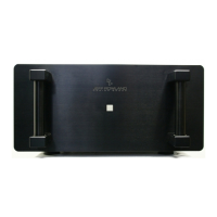
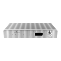
Rear Panel
(Note: All of the switches described below can be switched, if desired, while
the Amplifier is operational and playing music.)
1 INPUT SELECT switch: This switch selects either the RCA single-
ended inputs or the XLR balanced inputs. Note: When the RCA position
is selected, pin 2 of the XLR input is shorted to pin 1.
2 XLR INPUT PHASE switch: This switch selects between two XLR
connector standards in use worldwide. The XLR standard of associated
equipment should be noted and matched with the Model 8T/Ti to
achieve correct absolute phase. The Amplifier is non-inverting with
respect to XLR Pin 3 when the switch is in the upper position.
Furthermore, the Amplifier is non-inverting with respect to XLR Pin 2
when the switch is in the lower position. Regardless of the standard
selected, this switch can be used to conveniently reverse the absolute
phase of the entire audio system when XLR balanced inputs are used.
Note: The XLR standard used worldwide assigns Pin 1 to ground or input
interconnect shield potential.
3 OVERALL GAIN switch: This switch selects between a high (32 dB) or
normal (26 dB) overall gain structure of the Amplifier.
4 INPUT MUTE switch: This switch removes the internal input signal
connection from the Amplifier input circuitry thus permitting input
interconnect cables to be removed or inserted safely without switching
the Amplifier off.
5 INPUT IMPEDANCE switch: This switch selects between a high
(36k) or low (600 ohm) input impedance at the balanced XLR input
jacks or unbalanced RCA jacks.
6 FRONT PANEL LAMP switch: When placed in the OFF position, this
switch will cease front panel illumination during listening. Front panel
indication of operational status is restored when the switch is returned
to the ON position.
Front & Rear Panel Function Controls