T
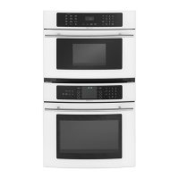
Built-In 27"& 30" t
Electric Combination Wall Ovens 303.6..oE omiJENN'AIR,.o,... L,s,.4. 50.01
INSTALLATION
INSTRUCTIONS
PART NO. 210410
Model numbers covered by these instructions: WM27160, WM27260, WM27460,WM30460
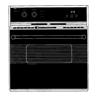
COMBINATIONWALLOVEN CUTOUT
1-1/4" Dia Conduit Access Hole* 1-1/4" Dia Conduit Access Hole* _--B-_---- A----_I
5/5" Plywood Floor (Must Support 250 Ibs.) 5/8" Plywood Floor (Must Support 250 Ibs.)
- -
A 27 MIN 68.58 MIN A 30 MIN 76.20 MIN ..------------- I
B 24 MIN 60.96 MIN B 24 MIN 60.96 MIN
C 44-1/2±1/16 113.03±.16 C 44-1/2±1/16 113.03 ±.16
D 23-1/2 MIN 59.69 MIN D 23-1/2 MIN 59,69 MIN C 1
E 25-1/2±1/16 64.77:L .16 E 28-3/16±1116 71.60±.16
F 44-15116 114.14 F 44-15116 114.14 1 r
G 26-3/4 67.95 G 29-5/4 75.57 •
H 24-7/16 62.07 H 24-7/16 62.07
I 4 to 20 t 0.2 to 50.8 I 4 to 20 10.2 to 50.8 __
• Hole must be cut as close to comer of cabinet as possible. _'_E
I Do not block air intake slots along bottom of oven
INSTALLATION
• Cut hole in cabinet to mount oven. Cutout in cabinetshouldbe levelandstraight.Note:Thereare no provisionsto levelthe uni
afterit is installed.Anoventhatis notlevel couldcause poorbakingresults,
2. Installplywoodflooras shownabove.
3. Attachunittothe cabinetwith6 No. 8"flat headscrewssuppliedinsideofenvelopecontainingthese instructions.Pre-ddllhole.=
incabinetfor attachment screwsusing1/8"drill.Oven mountingholesare providedinsidetrim.
4. See instructions"ElectricalConnections"forelectricalhook-up.
5. See Fig. 1 forlowertrim installation.
6. See User'sManualfor operatinginstructions.
Fig. 1 _
Removelowerscrewsfrom hingereceptacle
plates. Alignlowertrim andreinstallscrews iv