A
cover on the rear of the gear carrier housing permits the inspection and
flushing of the differential assembly without dismantling the axle.
The axle gear ratio is stamped on a tag attached to the assembly by one of the
rear cover screws. The axle serial number is stamped on the gear carrier housing
and should always be referred to when corresponding with reference to any
particulzr
unit.
In the event of trouble through any cause, wherever possible
it
is strongly
recommended that use should be made of the factory reconditioning service.
It should be clearly understood that the adjustment of the Hypoid Bevel axle
is more complex than that necessary for the satisfactory performance of the spiral
bevel.
For rear axle lubrication, see instructions on Page
7.
FUEL
SYSTEM.
Fuel Pump.
The fuel tank is mounted aft of the rear axle and is of 15 gallons capacity-l2
gallons main,
3
gallons reserve.
The
3
gallons reserve are not metered on the gauge.
From this tank fuel is fed to the carburetter by an A.C. mechanical pump mounted
on the
L.H.
side of the engine crank case. A priming lever is fitted to enable the
carburetter to be primed by hand (See Fig.
2,
Page 5). This should be used if the
carburetter float chamber has just been replaced after cleaning, to save an excess of
strain on the battery through using the starter to pump fuel through the system.
Approximately every 5,000 miles the strainer gauze in the fuel pump should be re-
moved and cleaned.
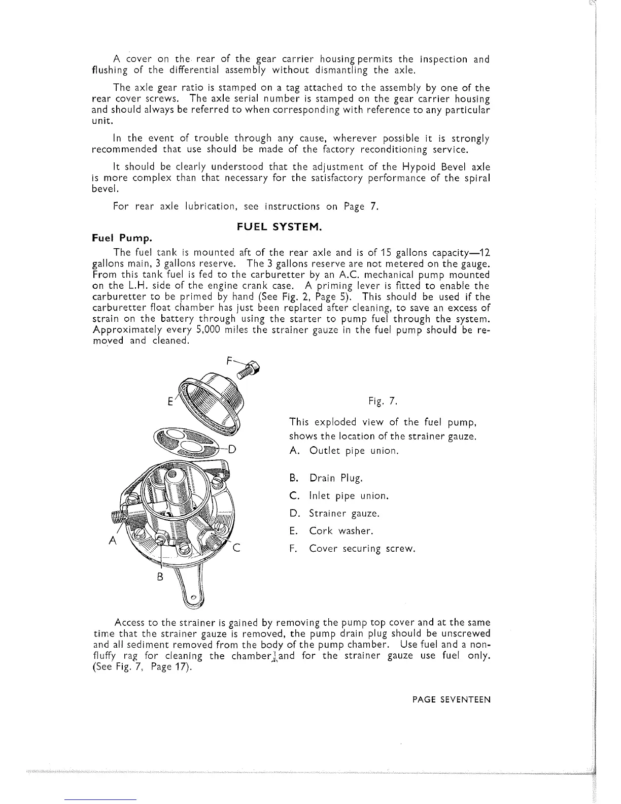
Fig. 7.
This exploded view of the fuel pump,
shows the location of the strainer gauze.
A. Outlet pipe union.
B.
Drain Plug.
C.
Inlet pipe union.
D.
Strainer gauze.
E.
Cork washer.
F.
Cover securing screw.
Access to the strainer is gained by removing the pump top cover and at the same
time that the strainer gauze is removed, the pump drain plug should be unscrewed
and all sediment removed from the body of the Dump chamber. Use fuel and a non-
,
a
fluffy rag for cleaning the chamber2,;nd for the strainer gauze use fuel only.
(See Fig.
7,
Page 17).
PAGE SEVENTEEN
 Loading...