EasyManua.ls Logo

jenway 3520 - User Manual

jenway 3520
40 pages
Print Icon
To Next Page IconTo Next Page
Loading...
Instruction Manual
352 050/REV B/01-17
pH/mV Temperature Meter
Model 3520

Questions and Answers

  • D
    Daniel LeeAug 17, 2025
    Why does my jenway 3520 display drifting erratic readings?
    • M
      Mark MyersAug 18, 2025
      If your Jenway Multimeter displays drifting, erratic readings, the issue might stem from an electrode fault. To resolve this, test the 3520 using a BNC cap, and if necessary, replace the electrode.
  • J
    Jacob MurphyAug 20, 2025
    What does ERROR SLOPE mean on my Jenway Multimeter?
    • T
      Tammy WhiteAug 20, 2025
      If your Jenway Multimeter shows an 'ERROR SLOPE', it typically indicates an electrode problem. Try testing the 3520 with a BNC cap. If the issue persists, replace the electrode.
  • J
    James KennedyAug 22, 2025
    What to do if my jenway 3520 Multimeter is unable to recognise the buffer?
    • M
      Matthew MeyerAug 23, 2025
      If your Jenway Multimeter is unable to recognize the buffer, ensure the buffer type is correct. Use AUTO for Jenway supplied buffers and replace the buffers if needed. You can also test the 3520 with a BNC cap and consider replacing the electrode.
  • A
    Alisha HahnAug 25, 2025
    Why can't I calibrate my Jenway Multimeter?
    • E
      Eric CochranAug 26, 2025
      If your Jenway Multimeter won't calibrate, this is often due to an electrode fault. Test the 3520 using a BNC cap. If the problem continues, replace the electrode.
  • T
    Tara FergusonAug 27, 2025
    What does ERROR EO mean on my jenway 3520?
    • A
      Ashley BarnettAug 27, 2025
      If your Jenway Multimeter displays 'ERROR EO', it indicates a buffer problem. Try using freshly prepared buffers to resolve this issue.
  • J
    Jamie HolmesAug 30, 2025
    Why are temperature readings incorrect on my jenway 3520?
    • C
      Carol FosterAug 30, 2025
      If your Jenway Multimeter temperature readings are incorrect, the temperature probe may be faulty. Check the 3520 and replace the temperature probe.
  • B
    Betty ScottSep 1, 2025
    Why is the display erratic on my Jenway Multimeter?
    • R
      Richard HancockSep 2, 2025
      If the display of your Jenway Multimeter is erratic, it might be due to the power supply. Make sure to use the supplied 9V ac power supply, as using other units can cause the 3520 not to operate correctly.
  • M
    Michele SmithSep 4, 2025
    Why are temperature readings fluctuating on my Jenway Multimeter?
    • J
      jeremy91Sep 4, 2025
      If your Jenway Multimeter temperature readings are fluctuating, it could be because of a faulty temperature probe. Check the 3520 and replace the temperature probe.
  • R
    Ricky BauerSep 6, 2025
    How to fix no display on Jenway Multimeter?
    • C
      Craig NicholsSep 6, 2025
      If your Jenway Multimeter display is blank, check the power supply. Ensure that the correct 9V ac power supply is properly connected and switched on.
  • C
    Christopher PerezSep 9, 2025
    What to do if Manual temp not set on my jenway 3520 Multimeter?
    • E
      Eugene AguilarSep 9, 2025
      To address the 'Manual temp not set' message on your Jenway Multimeter, set the meter to read °C and adjust the temperature against a calibrated thermometer.

Summary

Safety Precautions

Introduction and Specifications

Instrument Description

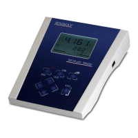
The Model 3520 is a fully specified laboratory pH/mV/Temperature meter that includes full support for good laboratory practices (GLP).

Instrument Specifications

Lists technical specifications including pH, mV, temperature ranges, resolution, accuracy, input impedance, ATC, buffer selection, outputs, clock, GLP, display, languages, power, size, and weight.

Installation Guide

Unpacking and Included Items

Details the items to check after unpacking the Model 3520, including the meter, electrodes, probes, and accessories.

Initial Installation Steps

Instructions for connecting the ATC and pH electrode, positioning the unit, and connecting the power supply.

Display Overview

Display Elements and Symbols

Describes display elements like annunciators, symbols, and clock, and their meanings.

Keypad Operation

Keypad Functionality

Details the functions of ESC, CAL/CLR, Print, Arrow keys, and STO keys for navigation and operation.

Connectivity and Outputs

Rear Panel Connections

Details the rear panel sockets: Ref, pH, Temp, Alarm O/P, RS 232, Power In, and Analog Out for connections.

Operation Fundamentals

Theory of pH Measurement

Explains pH as a measure of acidity/alkalinity and its relation to ion concentration.

pH Measurement Principles

Describes pH measurement using meters, electrodes, and factors affecting accuracy.

Calibration Preparation

Buffer Solution Preparation and Temperature Values

Emphasizes buffer preparation and the importance of measuring buffer temperature for accurate calibration.

Electrode Handling and Care

Electrode Handling and Maintenance Guidelines

Provides guidelines for electrode care: rinsing, storage, handling, bubble removal, and specific electrode types.

Configuration Settings

Instrument Setup: Resolution, Language, Display

Allows setting pH/mV Resolution, Language, and LCD Brightness.

Calibration Setup

Temperature Setup Options

Allows selection of temperature units (°C/°F) and manual temperature setting.

Calibration Setup Options

Allows selection of calibration points (1, 2, or 3) and buffer types (Auto or Manual).

Advanced Configuration

Alarm Settings and GLP Setup

Configures alarms, calibration reminders, user IDs, and batch IDs for GLP compliance.

Security and Data Logging

Security Setup Options

Sets up security codes for access control.

Data Logging Setup Configuration

Configures data logging parameters like event, destination, and interval.

Endpoint Detection and Clock Settings

Endpoint Detection and Clock Settings

Configures endpoint detection, audible alarm, clock display mode, date format, time, and date.

pH Calibration Procedures

Manual Temperature Compensation Calibration

Step-by-step guide for calibrating with pH buffers using manual temperature compensation.

Automatic Temperature Compensation Calibration

Details calibration with pH buffers using automatic temperature compensation.

Error Codes and Troubleshooting

Error Code Descriptions

Explains common error messages like EO limits, slope limits, and buffer recognition.

Millivolt Measurement Modes

Absolute and Relative Millivolts Measurement

Describes absolute mV for monitoring and relative mV for zeroing offset voltage.

Performing Measurements

Measurement Procedures: mV, Temperature, pH

Guides on performing measurements in mV, temperature (ATC/manual), and pH modes.

Status and Results Review

Calibration Status Display

Shows calibration data and performance metrics like Eo value and slope efficiency.

Data Logging and Accessing Stored Results

Configures data logging and explains how to navigate and view stored results.

GLP Functions and Security

GLP Setup and Security Features

Covers GLP functions like calibration reminders, user/batch IDs, and security code setup.

Maintenance

General Maintenance and Electrode Cleaning

Recommends keeping surfaces clean and provides methods for cleaning electrodes.

Accessories and Spares

Optional Accessories and Buffer Solutions

Lists optional accessories, electrodes, buffer solutions, and miscellaneous items.

Spare Parts List

Lists spare parts available for the Model 3520.

Interfacing and Connectivity

Analogue Output and RS232 Interface

Details analogue output sockets and RS232 interface connections.

RS232 Communication and Remote Control

RS232 Communication Parameters

Specifies baud rates, data bits, parity, and stop bits for RS232 communication.

Keypad Emulation via RS232

Explains keypad remote control via RS232 interface, mapping numeric codes to functions.

Printing and Alarms

Printing Methods and Output Content

Describes printer connection methods and the content of printouts.

Alarm Outputs Functionality

Details the two open collector alarm outputs and their setup.

Troubleshooting Guide

Troubleshooting Common Faults

Lists common faults, causes, and actions for issues like display errors, calibration problems, and printing failures.

Functional Checks and Reset

Functional Check Procedure

Describes how to perform a functional check using a BNC shorting cap.

Instrument Reset Procedure

Outlines the steps to reset the instrument to default values.

Regulatory Compliance

EU Declaration of Conformity Details

Provides product details, conformity to EU directives and standards, and declaration signature.

jenway 3520 Specifications

General IconGeneral
Continuity TestYes
Diode TestYes
Data HoldYes
Continuity BuzzerYes
DC Voltage Ranges200mV, 2V, 20V, 200V
AC Voltage Ranges200V
DC Current Ranges200μA, 2mA, 20mA, 200mA, 10A
Resistance Ranges200Ω, 2kΩ, 20kΩ, 200kΩ, 2MΩ
Safety RatingCAT II 600V
Power Supply9V battery

Related product manuals