Figure 6-2
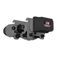
2. Align tabs on top of hoist (Figures 6-3,6-4) to
holes on underside of trolley. Secure with the
existing pins, washers and hex nuts.
The hoist should be oriented so that the
electrical strain reliefs on hoist and trolley are
at the same end. Make sure hoist is securely
mounted.
Figure 6-3
Figure 6-4
3. Bring the trolley power cable into the hoist
through the cable gland. See Figure 6-5.
Connect the four wires from the trolley cable to
the KM1 contactor, as described in Figure 6-5.
Figure 6-5
4. Locate the grey and orange wires in the hoist.
See Figure 6-6. The grey wire will control the
forward movement of the trolley. The orange
wire will control the reverse movement of the
trolley.
5. Bring the trolley control cable through the
second gland on the same side of the hoist,
and connect it as follows.
Connect #1 Red wire to port A2 of the KM3
contactor.
Connect #2 White wire to the grey wire.
Connect #3 Black wire to the orange wire.
Connect E grounding wire to the ground plate.
Note: if you connect the #2 White wire to the
orange wire (instead of the grey), the motor
movement will be reversed.
Figure 6-6
6. Trolley and hoist are now connected. Remove
the chain support from atop the trolley.
7. Proceed to sect. 7.0 for electrical connections.