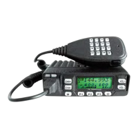
JT220M
5
CIRCUIT DESCRIPTION
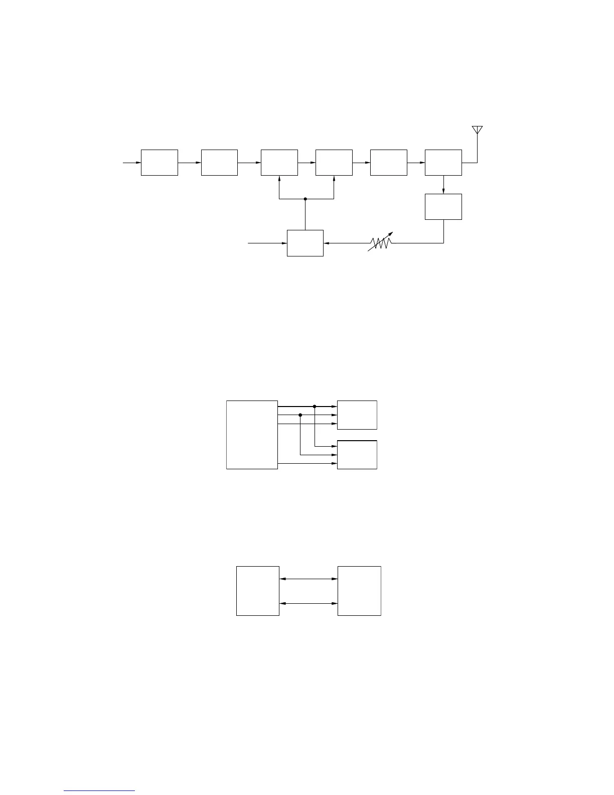
at the antenna end and to stabilize transmission output at voltage and temperature variations. (See Fig.
9.)
Fig. 9 APC Circuit
Control Circuit
The CPU carries out the following tasks (See Fig. 10.):
1) Controls the WIDE, NARROW, TX/RX outputs.
2) Controls the display unit.
3) Controls the PLL (U205).
4) Controls the D/A converter (U505) and adjusts the volume, modulation and transmission power.
Fig. 10 Control circuit
Memory Circuit
The transceiver has an 64k-bit EEPROM (U6). The EEPROM contains adjustment data. The CPU (U2)
controls the EEPROM through two serial data lines. (See Fig. 11.)
Fig. 11 APC Circuit
Display Circuit
The CPU (U2) controls the display LCD and LEDs. When power is on, the CPU will use the P12 line to
control the LCD illumination backlight LEDs.
The brightness function is controlled by the switch Q6 and Q7.
The LCD driver (U3) and CPU (U2) communicate through the CS, WR, DI, lines. (See Fig. 12.)
CK
D/A
DT
LD
LE
U505
converter
U205
PLL
U2
CPU
U6
EEPROM
U2
CPU
RF AMP
Q220
DRIVE STAGE
Q212
DRIVE AMP
Q214
FINAL AMP
Q216
ANT
ANT SW LPF
POWER
DET
D230,D231
APC
CONTROL
VR200
U204
14pin
U505
PC
D210,D211
D203


 To Next Page