EasyManua.ls Logo

JLG 330LRT - User Manual

JLG 330LRT
234 pages
Print Icon
To Next Page IconTo Next Page
Loading...
Service and Maintenance Manual
Models
330LRT
430LRT
PVC 1910
31215079
Se
ptember 13, 2019 - Rev A
AS/NZS
Go to Discount-Equipment.com to order your parts

Table of Contents

Questions and Answers

  • M
    mackenzie89Aug 4, 2025
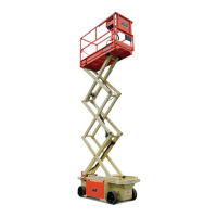
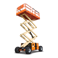
    What to do if my JLG 330LRT Scissor Lifts won’t shift or is slow to start?
    • E
      Erin DodsonAug 4, 2025
      If your JLG Scissor Lift won’t shift or is slow to start, it could be due to obstructed or restricted flow through the servo control signal lines, which can result in slow or no shift conditions within the motor. Ensure that the signal lines are not obstructed or restricted and that the signal pressure is adequate to shift the motor. Also, the supply and drain orifices determine the shift rate of the motor; obstruction will increase shift times. Ensure that the proper control orifices are installed in the motor and verify that they are not obstructed. Clean or replace them as necessary.
  • M
    Michael CummingsAug 25, 2025
    Why is my JLG Scissor Lifts system operating hot?
    • C
      Christian PageAug 26, 2025
      If your JLG Scissor Lift system is operating hot, it could be due to a few reasons. Insufficient hydraulic fluid may not meet the system's cooling demands; in this case, fill the reservoir to the proper level. Another cause could be a failing or obstructed heat exchanger, preventing it from meeting cooling demands. Ensure the heat exchanger is receiving adequate airflow and is in good operating condition; repair or replace it if necessary. Finally, a system relief valve that remains unseated for an extended period or fails can cause overheating. Repair or replace any malfunctioning relief valves and verify that the machine's loads are not excessive.
  • S
    Savannah VasquezNov 13, 2025
    Why is there excessive noise and/or vibration in my JLG 330LRT?
    • J
      Jonathan KimNov 13, 2025
      Excessive noise or vibration in JLG Scissor Lifts can stem from several causes. One potential cause is insufficient hydraulic fluid, which can lead to cavitation. To resolve this, fill the reservoir to the correct level and ensure an adequate oil supply to the motor, ensuring the lines are unobstructed. Another cause could be trapped air within the system lines or the motor, also resulting in cavitation. Make sure that all system lines and components are purged of air. A loose or incorrect shaft coupling can also produce vibrations. Verify that the correct coupling is installed properly on the shaft. Misaligned shafts can create excessive friction, leading to vibration. Ensure the shafts are properly aligned. Finally, hydraulic oil with viscosity above acceptable limits can cause cavitatio...

Summary

SECTION A. INTRODUCTION - MAINTENANCE SAFETY PRECAUTIONS

A GENERAL

Safety precautions for MEWP maintenance.

B HYDRAULIC SYSTEM SAFETY

Safety for high-pressure hydraulic systems.

C MAINTENANCE

General maintenance safety precautions and rules.

REVISON LOG

Original Issue

Document's initial release details and date.

SECTION 1 - SPECIFICATIONS

1.1 Specifications

Detailed machine and component specifications.

1.2 Serial Number Location

Location of serial number plates on the machine.

1.3 Lubrication

Hydraulic and engine oil specifications and recommendations.

1.4 Hydraulic Pressure Settings

System pressure settings for various hydraulic components.

1.5 Hydraulic Cylinder Specifications

Bore, stroke, and rod diameter for hydraulic cylinders.

1.6 Engine Specifications

Engine details including emissions, fuel type, and performance.

1.7 Elevation;Tilt Limit Settings

Machine tilt cutout settings for safety and operation.

1.8 ThreadLocking Compound

Recommended threadlocking compounds for various applications.

1.9 Torque Charts

Torque specifications for SAE and Metric fasteners.

SECTION 2 - GENERAL

2.1 Machine Preparation, Inspection, and Maintenance

Procedures for preparing, inspecting, and maintaining the machine.

2.2 Preventive Maintenance and Inspection Schedule

Schedule for periodic maintenance and inspections.

2.3 SERVICE AND GUIDELINES

Information on servicing and maintenance procedures.

2.4 LUBRICATION AND INFORMATION

Hydraulic system and oil information, lubrication recommendations.

2.5 SERVICE MAINTENANCE COMPONENTS

Specific maintenance steps for components like scissor arm safety prop.

2.6 CYLINDER DRIFT TEST

Methods for measuring acceptable cylinder drift.

2.7 PINS AND COMPOSITE BEARING REPAIR GUIDELINES

Guidelines for inspecting and repairing pins and composite bearings.

SECTION 3 - CHASSIS, PLATFORM, & SCISSOR ARMS

3.1 Operating Characteristics

How leveling jacks, generator, lift, and drive systems function.

3.2 TIRES, WHEELS & DRIVE ASSEMBLY

Procedures for tire damage, replacement, and wheel installation.

3.3 DRIVE HUB

Roll and leak testing, tightening bolts, and oil information.

3.4 DRIVE MOTOR (SAUER)

Description, removal, and installation of the drive motor.

3.5 AXLE INSTALLATION

Procedures for removing and installing axles.

3.6 Steer Installation (All Markets Except for CE and JAPAN)

Procedures for steering cylinder and spindle installation.

3.7 Steer Installation (CE and Japan Markets)

Steering installation procedures specific to CE and Japan markets.

3.8 LEVELING JACKS (IF EQUIPPED)

Procedures for removing and installing leveling jack cylinders.

3.9 PLATFORM

Platform removal and installation procedures.

3.10 SCISSOR ARMS

Procedures for removing lift cylinders and scissor arms.

3.11 SIDE COMPARTMENT COVERS

Procedures for removing and installing side compartment covers.

3.12 GROUND CONTROL STATION

Procedures for removing and installing the ground control station.

3.13 BATTERY

Procedures for removing and installing the battery.

3.14 FUEL TANK

Procedures for removing and installing the fuel tank.

3.15 HYDRAULIC TANK

Procedures for removing and installing the hydraulic tank.

3.16 Kubota Engine

Engine tray swing-out, removal, and installation procedures.

Generator (If Equipped)

Procedures for generator removal and installation.

SECTION 4 - BASIC HYDRAULIC INFORMATION & SCHEMATICS

4.1 Cylinders - Theory of Operation

Explanation of double-acting and single-acting cylinder functions.

4.2 Valves - Theory of Operation

Explanation of solenoid, relief, and crossover relief valves.

4.3 Cylinder Checking Procedure

Procedures for checking cylinder seals and operation.

4.4 Oscillating Axle - Lockout Cylinder Test (If Equipped)

Testing procedure for the oscillating axle lockout cylinder.

4.5 Drive Pump Pre-fill Procedure

Procedures for pre-filling drive pump housing.

4.6 Drive Pump Start-up Procedure

Steps for safely starting up a new or reinstalled drive pump.

4.7 Hydraulic Component Start-Up Procedures & Recommendations

General start-up procedures for hydrostatic systems.

4.8 Hydraulic Valves

Identification and removal/installation of main hydraulic valves.

4.9 GEAR PUMP

Information on gear pumps, including specifications.

4.10 AXIAL HI 45 PUMP

Repair instructions, start-up, and component details for the axial pump.

4.11 CHARGE PUMP FILTER

Procedures for removing and installing the charge pump filter.

4.12 CYLINDER REPAIR

General procedures for cylinder disassembly and inspection.

4.13 CYLINDER ASSEMBLIES

Exploded views and details of steer and lift cylinders.

4.14 HYDRAULIC SCHEMATICS

Hydraulic circuit diagrams for troubleshooting and understanding.

SECTION 5 - JLG CONTROL SYSTEM

5.1 ANALYZER

Connecting and using the JLG Analyzer for diagnostics.

5.2 ANALYZER MENU FLOW CHART

Visual guide to navigating the Analyzer menu structure.

5.3 DIAGNOSTIC TROUBLESHOOTING CODES (DTC’S) AND FLASH CODES DESCRIPTION

List of DTCs, flash codes, and their meanings for troubleshooting.

5.4 CHASSIS TILT SENSOR INSTALLATION

Procedures for installing and calibrating the chassis tilt sensor.

5.5 LOCATION OF ADDITIONAL SENSORS

Identifying the placement of various sensors on the chassis.

5.6 CALIBRATION PROCEDURES

Step-by-step guide for calibrating various sensors and systems.

5.7 SERVICE MODE PROCEDURES

Accessing and using service mode for specific functions like ECM override.

5.8 MACHINE CONFIGURATION AND PROGRAMMING SETTINGS

Settings for configuring machine personality and market-specific options.

SECTION 6 - LSS SETUP;CALIBRATION;SERVICE

6.1 CONNECTING THE JLG CONTROL SYSTEM ANALYZER

Instructions for connecting the JLG Analyzer to the control system.

6.2 HELP MENU & FAULT CODES

Using the Help Menu to diagnose system faults and understand codes.

6.3 DIAGNOSTIC MENU

Accessing and understanding the Diagnostic Load Menu for LSS.

6.4 PERSONALITIES

Adjusting LSS performance parameters within the Personalities menu.

6.5 MACHINE SETUP MENU

Configuring the Load Sensing System (LSS) within the Machine Setup menu.

6.6 CALIBRATION MENU

Accessing and performing load calibration for the LSS module.

6.7 SERVICE

Description of Load Sensing System components and their function.

6.8 CALIBRATION

Procedure and testing for calibrating the Load Sensing System.

6.9 TROUBLESHOOTING

Troubleshooting common difficulties with the LSS module.

SECTION 7 - GENERAL ELECTRICAL INFORMATION & SCHEMATICS

7.1 GENERAL

General electrical information and schematics for troubleshooting.

7.2 MULTIMETER BASICS

Using a multimeter for various electrical measurements.

7.3 APPLYING SILICONE DIELECTRIC COMPOUND TO ELECTRICAL CONNECTIONS

Procedure for applying silicone dielectric compound to connectors.

7.4 DIELECTRIC GREASE APPLICATION

Guidance for applying dielectric grease to various connector systems.

7.5 AMP CONNECTOR

Procedures for AMP connector assembly and disassembly.

7.6 WORKING WITH DEUTSCH CONNECTORS

Procedures for assembling and disassembling Deutsch DT/DTP connectors.

7.7 SWITCHES

Basic checks for switches and limit switches.

7.8 ELECTRICAL SCHEMATICS

List of electrical schematic sheets for the 330/430LRT.

JLG 330LRT Specifications

General IconGeneral
BrandJLG
Model330LRT
CategoryScissor Lifts
LanguageEnglish

Related product manuals