Do you have a question about the JM Concept XALIS Series and is the answer not in the manual?
Essential safety and handling guidelines before operating the device.
Steps for proper setup and initial programming sequence.
Device compliance with environmental and industrial standards.
Physical size specifications and cut-out dimensions for installation.
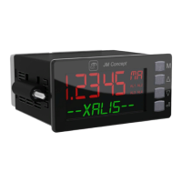
Diagram showing the device's front panel components and labels.
Configuration options for the device's numerical and alphanumeric display.
Setting the display color for numerical or alphanumeric lines.
Automatic color change based on relay status or alarms.
How to view input values in physical or programmed format.
Displaying output values, percentages, and relay states.
Methods for programming the device via front panel or PC.
Adjusting the offset value for all input types.
Procedure for setting the tare function for process inputs.
Using the simulation function to test outputs without affecting inputs.
Setting high and low limits for output values.
Cold Junction Compensation for thermocouple inputs.
How the device detects and signals sensor breaks.
Creating custom output functions by segmenting input signals.
Creating PTC/NTC curves via input signal segmentation.
Configuring alarm thresholds, hysteresis, and temporization.
Function to acknowledge or reset active alarms.
Function to store or memorize alarm events.
Miscellaneous functions like resolution, filtering, and display settings.
Detailed technical specifications of the device's performance.
Electrical isolation specifications between different device terminals.
Diagrams showing terminal connections for inputs, outputs, and communication.
Explanation of how to use the device's buttons for navigation and operation.
Display of current measurement values on the device.
The top-level menu structure for device configuration.
Configuration settings for current input signals.
Configuration settings for voltage input signals.
Configuration settings for resistance (e.g., PT100) input signals.
Configuration settings for RTD temperature sensor inputs.
Configuration settings for thermocouple temperature sensor inputs.
Configuration options for analog and relay outputs.
Setting up alarm conditions, thresholds, and relay behavior.
Configuration of general device parameters and communication settings.
Configuration of RS485 communication parameters like baud rate and address.
Customization options for the device display's color and brightness.
Settings for controlling access and authorization for programming.
Defining specific alarm thresholds and their associated logic.
Enabling and configuring the input simulation mode.
Procedure for zeroing or taring the input measurement.
| Type | Laser Distance Meter |
|---|---|
| Accuracy | ± 1.5 mm |
| Laser Type | 635 nm, <1mW |
| Protection Class | IP54 |
| Laser Class | Class 2 |
| Units of Measurement | m, in, ft |
| Display | LCD with backlight |
| Power Supply | 2 x AAA batteries |
| Resolution | 0.001m |
| Operating Temperature | 0°C to 40°C |