- 14 -
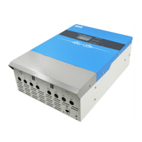
Picture 8 Diagram of controller terminal
• Remove two terminal-cover screws on the side of the controller and then remove the cover (show
as the picture 7)
• Connect the battery positive and negative electrode cable, load cable and photovoltaic board cable
in turn (show as the picture 8).
• Connect the communication cable to 2pin lotus terminal. One end is inserted into the RS485
terminal on the controller, the other end is connected to the converter for RS485. Then connect
RS485 converter to the PC. And if the controller is in parallel operation, please connect RS485
communication cables hand in hand to the controller first.
• Remote temperature probe is inserted into the TEMP terminal of the controller.
• Connect the relevant cables and ensure a firm connection. Put back the terminal-cover and tighten
the screws.
• Fix the controller.
• Turn on the air break switch in the battery side and then in the photovoltaic panels side. Open the
controlle. The LED lights on the display flash several times and then the controller begin to work.
Warning:
• In order to install safely, we recommend such a connection order. However, installation not in
accordance with this sequence will not damage the controller.
 Loading...