Do you have a question about the JNGE Power JND-X Series and is the answer not in the manual?
Defines safety symbols used in the manual and their implications.
Provides critical safety notices regarding professional installation and warranty conditions.
Emphasizes compliance with standards, proper grounding, conductor size, and secure connections.
Warns against opening covers during operation and stresses professional maintenance after power disconnection.
Outlines the key features and benefits of the JND-X solar charge controller, focusing on optimization and protection.
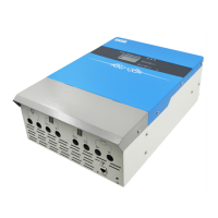
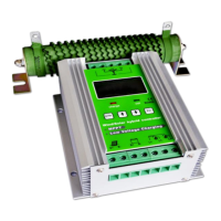
Illustrates the physical appearance of the JND-X controller with labeled components and provides a detailed appearance information table.
Presents the physical dimensions and weight of the JND-X controller in a table format.
Provides crucial notes and warnings for safe and proper battery installation and environmental considerations.
Details the steps for choosing an installation place, unpacking, checking, and fixing the controller, including a diagram.
Guides on the wiring sequence, battery connection, PV connection, and load connection, emphasizing safety and correct polarity.
Specifies the electrical parameters and voltage requirements for the photovoltaic array to ensure compatibility with the controller.
Provides requirements for cable type selection based on current rate, including wire diameter and AWG specifications.
Explains the meaning of the LED indicators (ERROR, CHARGE, LOAD) and their states for normal operation and faults.
Details button functions, LCD display information, and icon definitions for user interaction and monitoring.
Guides on setting general parameters and specific voltage thresholds like undervoltage protection.
Explains combination button functions for restoring factory settings and modifying ID addresses.
Details various protection mechanisms like reverse polarity, overvoltage, and overheating to safeguard the system.
Provides a list of common errors, possible reasons, and solutions for troubleshooting system issues like array overvoltage and battery faults.
Recommends regular inspections and cleaning for optimal long-term performance and safety.
Outlines the one-year free warranty, conditions for service, and company disclaimers regarding improper use.
Lists detailed electrical parameters including rated voltage, current, input power, and battery control parameters.
Provides a visual representation of the controller's physical dimensions and mounting information.
| Model | JND-X Series |
|---|---|
| Category | Controller |
| Charging Mode | PWM |
| Display | LCD |
| Cooling Method | Natural cooling |
| Application | Solar power systems |
| Rated Voltage | 12V/24V Auto |
| Max. Charging Current | 30A |
| Operating Temperature | -35°C to +55°C |
| Protection | Overload, short circuit, reverse polarity |
| Max Output Current | 20A/40A/60A |
| Efficiency | ≥98% |
| Dimensions | Varies by model |
| Weight | Varies by model |
| Max. Input Power | 390W (12V), 780W (24V) |