Anhui JNGE Power Co,. Ltd
Address: No.99 Yonghe Road, High-Tech Zone, Hefei City Anhui Province, China Mainland
Tel:0551-65372576 http://www.hfjnge.com
- 5 -
2.2 Product Introduction
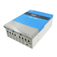
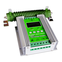
2.2.1 Appearance
Figure 2-1 JND-X controller appearance
Table 2-1 JND-X appearance information
Connect dc load positive pole
The battery provides energy to the
external dc load through the controller
Connect dc load negative pole
Connect the positive pole of pv
array 1
PV array main input (pv array wiring
priority main access)
Connect the negative pole of pv
array 1
Connect the positive pole of pv
array 2
Photovoltaic array auxiliary input
Connect the negative pole of pv
array 2
Connect the battery positive
electrode
Connect the battery negative
electrode
Realize the upper computer, WIFI
and GPRS communication monitoring
Controller starts and works normally
Display screen and buttons
Display and set various parameter
information of the controller
 Loading...