Models EELR538A and EELR539A
Models EELR540A and EELR541A
Installation, Operation and Maintenance
Page 8
Rev. 08/27/2021
15-18000-IOM-W.doc
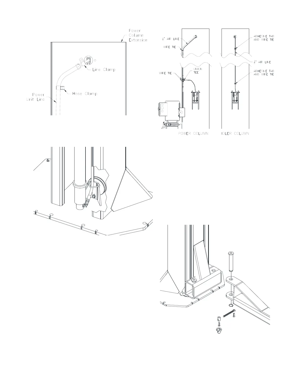
Fig. 13-Hose and Line Clamps
23) Hoses should connect to cylinders with a 90
degree elbow rotated 25 degrees upward and
be routed thru hose guide (Fig. 13B).
Fig. 13B-Hose Connection
24) B
E CERTAIN ALL FITTINGS AND CONNECTIONS ARE
TIGHT. IT IS THE INSTALLERS RESPONSIBILITY TO
INSURE SYSTEM IS LEAK
-FREE. Fill the Power Unit
with three gallons of clean 10wt anti-foam anti-
rust hydraulic oil or Dexron III ATF. D
O NOT USE
OILS WITH DETERGENTS.
L
OCK RELEASE
25) On the Power Column, attach the 1/8” air line
from the lock release air cylinder to the push-lock
tee fitting. Run another section of 1/8” air line
from the button valve to the tee (Fig. 14).
26) Connect the rest of the 1/8” air line to the top of
the tee and run it up the column attaching it to
the hydraulic line using wire ties (Fig. 14).
Fig. 14-Lock Release
27) After running the 1/8” air line along the hydraulic
line in the overhead and out the other opening in
the Idler Column (Fig. 14), run the air line down
the column using adhesive tab and wire ties.
Attach it to the lock release air cylinder (Fig. 14).
A
RM INSTALLATION
28) Lubricate the arm pin or carriage arm pin hole
with “anti-seize” and install the arms. Insure that
the arm restraint gears engage and disengage
properly. Arm restraints should disengage when
lift is fully lowered (Fig. 15).
29) Extend the footpad to both extents and apply
“anti-seize” to the retaining ring.
Fig. 15-Arm Installation
30) Make sure all the arm bolts are tight using a 3/8”
hex key. Slide all the arms out so they are fully
extended making sure that the male is retained
in the female.
 Loading...