Models EELR538A and EELR539A
Models EELR540A and EELR541A
Installation, Operation and Maintenance
Page 9
Rev. 08/27/2021
15-18000-IOM-W.doc
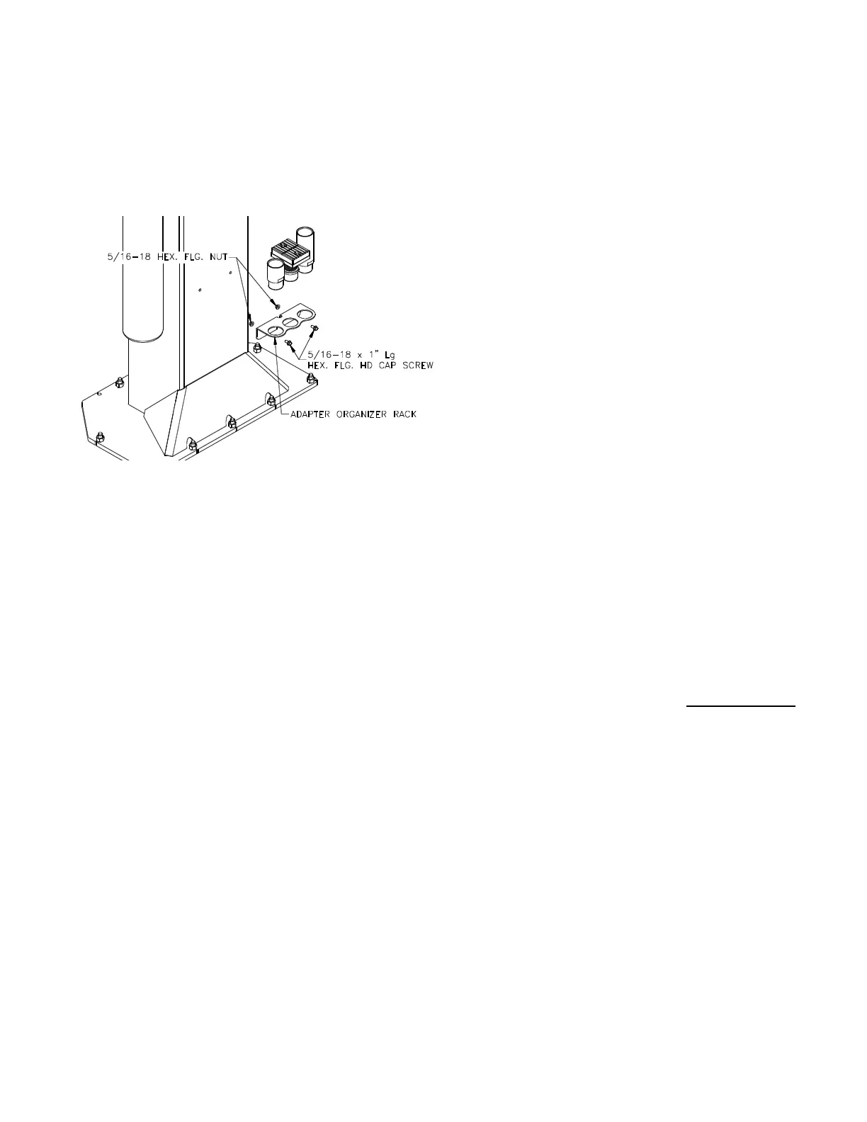
ADAPTER RACK INSTALLATION
31) Locate the two pre-drilled holes on the back of
each column 19” up from the top of the base
plate and tap 5/16”-18. Center the adapter rack
and attach with 5/16”-18 x 1" Lg hex flange cap
screw and 5/16”-18 hex flange nut (Fig. 16).
Fig. 16-Adapter Rack Installation
E
LECTRICAL
See Figure 17 for the following steps.
32) Wire tie Limit Switch cord to column hydraulic
line and power unit line.
33) Connect the Overhead Limit Switch Cord to
Power Unit as shown in Fig. 17.
34) Connect Power Unit to suitable electrical source
as shown in Fig. 17.
35) IMPORTANT:
AFTER WIRING HAS BEEN
COMPLETED
, TEST OPERATION OF POWER UNIT &
OVERHEAD LIMIT SWITCH. WHILE RAISING LIFT,
OPERATE
OVERHEAD SHUTOFF BAR. POWER UNIT
MOTOR SHOULD STOP WHEN SHUTOFF BAR IS
RAISED
.
F
INAL ADJUSTMENTS HYDRAULICS
36) Lower the lift to the floor and raise the lift
approximately one foot.
37) Start with Idler side first. Slowly and carefully
loosen the bleed plug on top of the cylinder just
enough to allow the entrapped air to escape.
Repeat for power side.
38) Raise lift 6 inches. Repeat step 36 until no air
comes out of cylinder.
39) Pressure test hydraulic system. Energize power
unit, raise lift to full rise and continue to run
motor for additional 10 seconds. (NOTE:
pressure relief will make a high pitch squeal
sound for these 10 seconds.) Check hydraulic
system for leaks.
40) Energize power unit again for 10 seconds. With
a clean rag, wipe down both cylinder rods. (The
cylinders are shipped with a small amount of
clear anti-corosive lubricant that will be forced
out through the wiper when the lift reaches full
rise.) If lubricant is not wiped clean from the
cylinder rod, the cylinder will apear to be
leaking.
S
YNCHRONIZING CABLES
41) Raise lift and insure carriages lower into same
lock position.
42) Adjust synchronizing cables so the tension is
equal in both cables and carriages are firmly
sitting on locks.
43) Cycle lift to insure that locks operate
simultaneously. Adjust if necessary.
O
WNER/OPERATOR CHECKLIST
44) Demonstrate the operation of the lift to the
owner/operator and review correct and safe
lifting procedures using the Lifting It Right
booklet as a guide.
45) Return all provided literature (including this
manual) to the literature pack envelope and
deliver the envelope to the
owner/operator/employer.
46) Complete the online warranty registration (refer
to the included warranty statement).
 Loading...